Food insulation board

A technology of plate body and protection switch, applied in the direction of coupling device, ohmic resistance heating parts, base/casing, etc., can solve the problems of occupying use space, limited use space, hindering the flexibility of personnel, etc., to improve structural stability, The effect of preventing foot swing and saving storage space

Pending Publication Date: 2022-04-29
中山市易之达电器有限公司
View PDF0 Cites 0 Cited by
  • Summary
  • Abstract
  • Description
  • Claims
  • Application Information

AI Technical Summary

Problems solved by technology

[0003]At present, the food insulation boards for household use on the market are all single-layered, and can only be placed flat on the dining table directly. The space is limited, and when there are many dishes, it is difficult to simultaneously Put down a lot of dishes, it is difficult to meet the needs of families wit

Method used


Image

  • Food insulation board
  • Food insulation board
  • Food insulation board

Examples


Embodiment 1

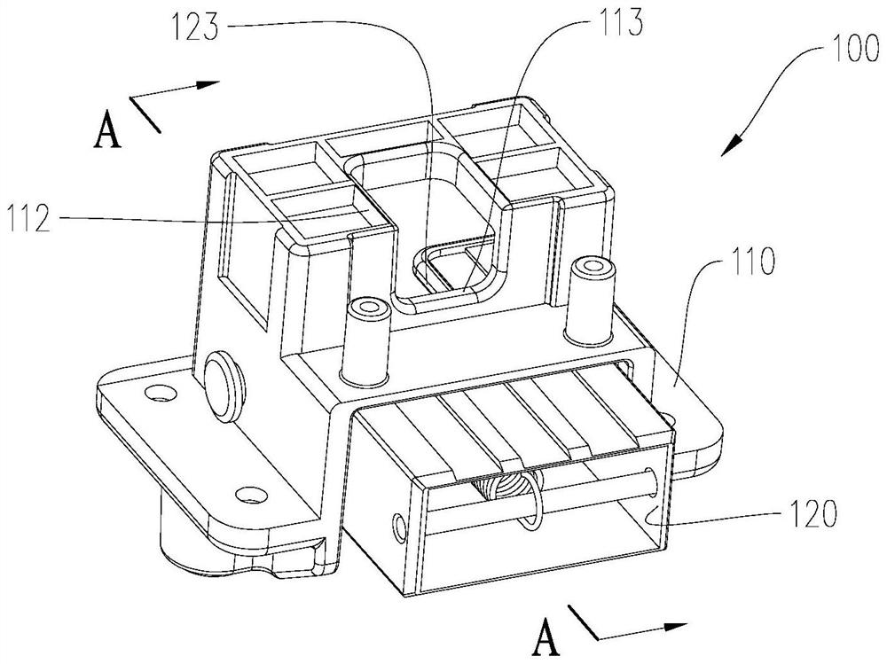
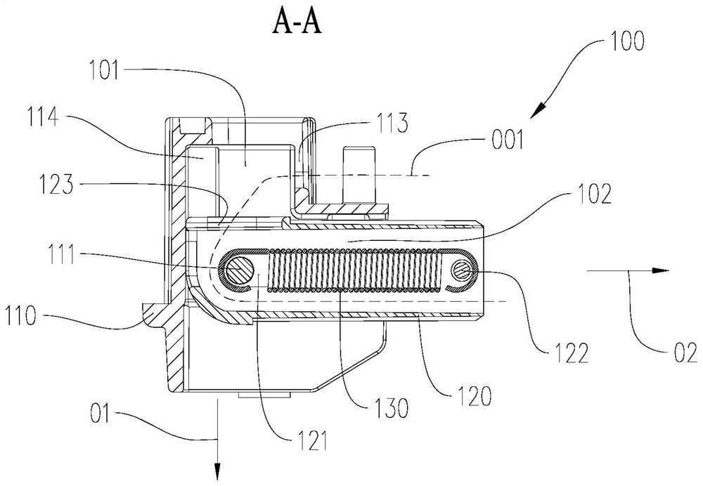
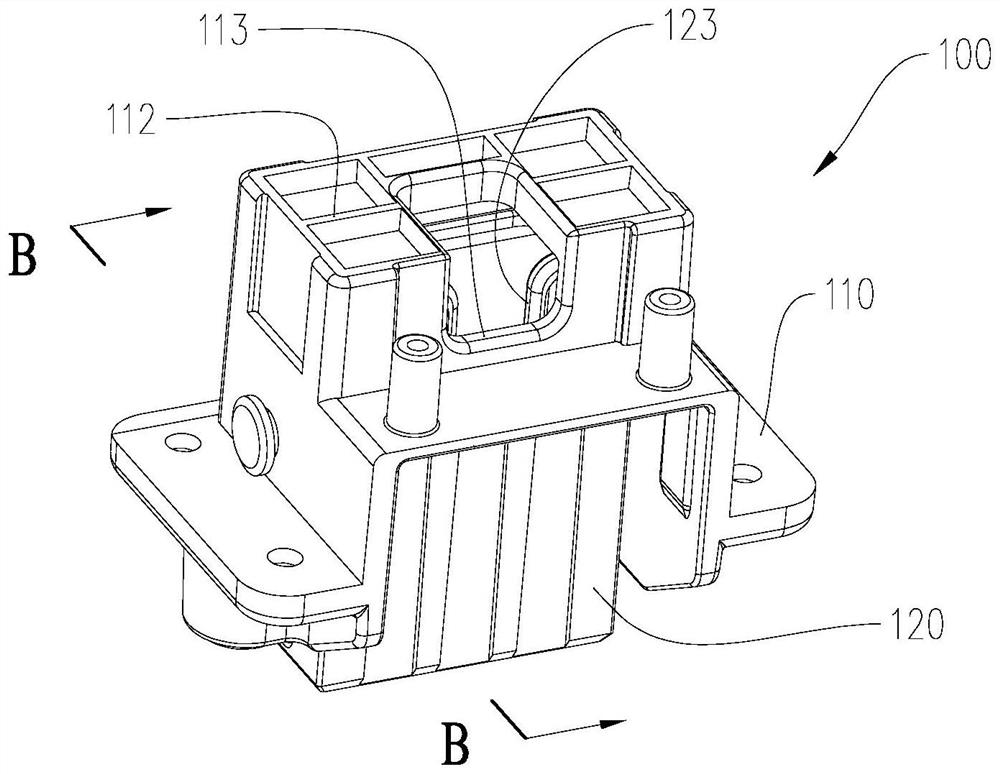
[0041] Such as Figure 1-2 As shown, the folding joint 100 is in a folded state.

[0042] Such as Figure 3-4 As shown, the folding joint 100 is in an extended state.

[0043]The fold joint 100 is used for the foot fold of the food warmer. The folding joint 100 includes a base 110 and a movable block 120 . The base 110 is provided with a first groove 101 extending along the unfolding direction 01 and a second groove 102 extending along the folding direction 02 , and the unfolding direction 01 intersects the folding direction 02 . The rotating shaft 111 is fixed on the base 110, located at the intersection of the first groove 101 and the second groove 102, and perpendicular to the plane formed by the unfolding direction 01 and the folding direction 02. The movable block 120 is rod-shaped, and the first end of the movable block 120 is provided with an elongated hole 121 extending along its axial direction, the rotating shaft 111 passes through the elongated hole 121, and the...

Embodiment 2

[0051] Such as Figure 5 As mentioned above, the difference between this embodiment and the previous embodiments is that there is no avoidance gap and corresponding reinforcing rib on the base 210 of the folding joint 200 , and there is no avoidance opening on the movable block 220 . In this way, the mold making process can be simplified and the manufacturing cost can be saved.

[0052] Examples of food warming boards:

[0053] Such as Figure 6 and Figure 7 As shown, the food warming board 1000 includes a first food warming board 1100 and a second food warming board 1200 .

[0054] The first food warming board 1100 includes a first board body 1110 and a first heating element (not shown in the figure) installed in the first board body 1110 . The switch 1111 is used to control the power on and off of the first heating element. The indicator light 1112 is used to indicate the power on and off of the first heating element. The first heating element is covered with a temper...


PUM


Abstract

The invention provides a food insulation board. The food insulation board comprises a first board body with a first heating element and a second board body with a second heating element. The first plate body is provided with at least two foldable foot parts distributed in the circumferential direction of the first plate body, and the second plate body is provided with foot seats distributed in the circumferential direction of the second plate body. Concave cavities are formed in the upper sides of the footstands, and when the feet are in the stretching state, the feet can be inserted into the concave cavities. The bottom of at least one pin is provided with a first electrode, and the first heating element is electrically connected with the first electrode through a first wire located in the pin. A socket matched with the first electrode is arranged in at least one concave cavity, and a second electrode is arranged on the socket. When the foot part is inserted into the cavity, the first electrode is connected with the second electrode. The first plate body can be mounted on the second plate body in a stacked manner, so that the desktop space is utilized to the greatest extent. And the whole double-layer food insulation board only needs one external power line, so that the space is further saved.

Description

technical field [0001] The invention relates to the field of household appliances, in particular to a food heat preservation board for food heat preservation. Background technique [0002] When the temperature is low, the dishes on the dining table tend to cool down and become cold, which is not conducive to eating. Food insulation boards arise at the historic moment, and its heating source is usually an electric heating tube or a heating wire placed under a ceramic plate or a glass plate. A power input interface, a power switch, a power indicator light and a temperature regulating device are usually arranged at the frame of the food insulation board. Thermostats are usually knobs, sliders, or buttons. Some food insulation boards are fixed power insulation boards without external temperature adjustment devices. [0003] At present, the food insulation boards for household use on the market are all single-layer, and can only be placed flat on the dining table directly. The...

Claims


Application Information

Patent Timeline
IPC IPC(8): A47J39/02H01R13/52H05B3/02
CPCA47J39/02H01R13/5202H05B3/02
Inventor 慈文龙
Owner 中山市易之达电器有限公司
Why Eureka
Try Eureka