
Integral wing and aileron driving device and mounting method

A driving device, integrated technology, applied in the direction of aircraft transmission, aircraft power device, aircraft power transmission, etc. problems, to achieve the effect of ensuring fluency and transmission capacity

Pending Publication Date: 2022-04-15
HUNAN AEROSPACE HUNAYU COMM TECH CO LTD
View PDF0 Cites 0 Cited by
  • Summary
  • Abstract
  • Description
  • Claims
  • Application Information

AI Technical Summary

Problems solved by technology

[0003] However, some of the existing transmission mechanisms are only suitable for the layout structure where the aileron is located at the wing root of the wing main body, that is, the end surface of the aileron is directly exposed to the drive part of the wing box, and the transmission is directly performed from the end surface. However, this transmission mode The applicable airfoil has low rudder efficiency and cannot be used for high-speed drones
Although some can be used for airfoils with ailerons arranged at the far end or in the middle of the wing body, the installation and disassembly of the transmission mechanism needs to be completed by dismantling the wing body. Wings that cannot be attached to the interior of a one-piece wing without a process separation surface

Method used


Image

  • Integral wing and aileron driving device and mounting method
  • Integral wing and aileron driving device and mounting method
  • Integral wing and aileron driving device and mounting method

Examples


Embodiment

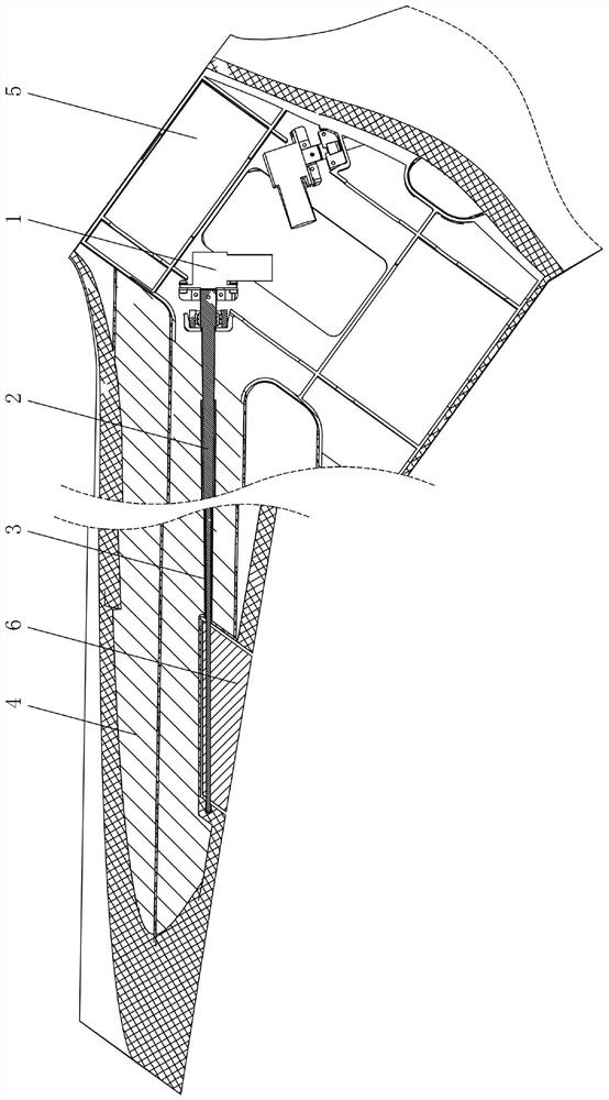
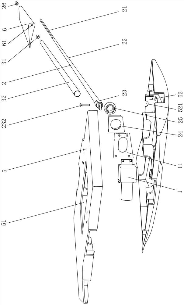
[0036] Such as figure 1 and figure 2 As shown, the integral wing and aileron driving device of the present embodiment is used on the high-speed unmanned aerial vehicle of the integral airfoil, that is, the wing main body 4 and the wing box 5 of the unmanned aerial vehicle adopt an integral molding process, without There is disassembly, no process separation surface, to ensure the smoothness of the lines.

[0037] Including the driving part 1, the transmission assembly 2 and the transmission accommodation cylinder 3, the transmission accommodation cylinder 3 is pre-embedded in the wing main body 4 which is integrally made with the wing box 5 with the opening 51, and is located in the wing main body 4. 6 is installed between the wing box 5 and arranged coaxially with the axis of rotation of the aileron 6 . The pre-embedded transmission housing 3 builds a channel connected between the drive member 1 and the aileron 6 in the wing box 5 during the wing preparation process, provi...


PUM


Abstract

The invention discloses an integral type wing aileron driving device and an installation method.The integral type wing aileron driving device comprises a driving part, a transmission assembly and a transmission containing cylinder, and the transmission containing cylinder is pre-buried in a wing main body integrally manufactured with a wing box with an opening and located between the installation position of an aileron in the wing main body and the wing box; the rotating shaft and the rotating shaft of the aileron are coaxially arranged; the transmission assembly is movably arranged in the transmission containing cylinder in a penetrating mode and can move in the axial direction when not connected with the driving piece, and one end of the transmission assembly is connected with or disengaged from the aileron located at the installation position. The driving part enters the wing box from the opening, is connected with the other end of the transmission assembly, limits the axial movement of the transmission assembly and drives the transmission assembly to rotate. The driving device has the advantages of being simple in structure, reasonable in layout, capable of being installed from a small opening, suitable for airfoils without process separation surfaces and with ailerons located at the far end or in the middle of the wing body and the like. The installation method of the driving device further has the advantages of being simple in step, convenient to operate, extremely small in space needed by operation and the like.

Description

technical field [0001] The invention relates to the technical field of high-speed unmanned aerial vehicles, in particular to an integral wing aileron drive device and an installation method. Background technique [0002] The wings of high-speed UAVs usually use thin airfoils with relatively small thickness to reduce air resistance and obtain good aerodynamic performance. However, due to the thinness of the wing, it is often impossible to arrange the aileron driving parts such as the steering gear in the wing body. The existing better solution is to place the aileron driving parts in the central wing box, and then transmit the driving force to the ailerons through a set of transmission mechanisms. [0003] However, some of the existing transmission mechanisms are only suitable for the layout structure where the aileron is located at the wing root of the wing main body, that is, the end surface of the aileron is directly exposed to the drive part of the wing box, and the tran...

Claims


Application Information

Patent Timeline
IPC IPC(8): B64C1/26B64C9/02B64C13/30
Inventor 金龙王浩李嘉祥
Owner HUNAN AEROSPACE HUNAYU COMM TECH CO LTD
Learn More