Auxiliary test device

A technology of test device and cross bar, which is applied in the field of building material mechanics test device, can solve the problems of unfavorable screw anchor installation characteristics, test result error, etc., and achieve the effect of convenient recording work and improving stability

Active Publication Date: 2022-04-08
YANGZHOU UNIV
View PDF7 Cites 0 Cited by
  • Summary
  • Abstract
  • Description
  • Claims
  • Application Information

AI Technical Summary

Problems solved by technology

[0003] However, there are few test devices for studying the installation characteristics of screw anchors. The existing test devices are all assembled by the experimenters themselves, and the inability to coordinate and cooperate with each part may cause the test There are unavoidable errors in the results, which is not conducive to the study of the installation characteristics of the screw anchor

Method used


Image

  • Auxiliary test device
  • Auxiliary test device
  • Auxiliary test device

Examples


Embodiment Construction

[0031] The technical solutions provided by the present invention will be described in detail below in conjunction with the accompanying drawings.

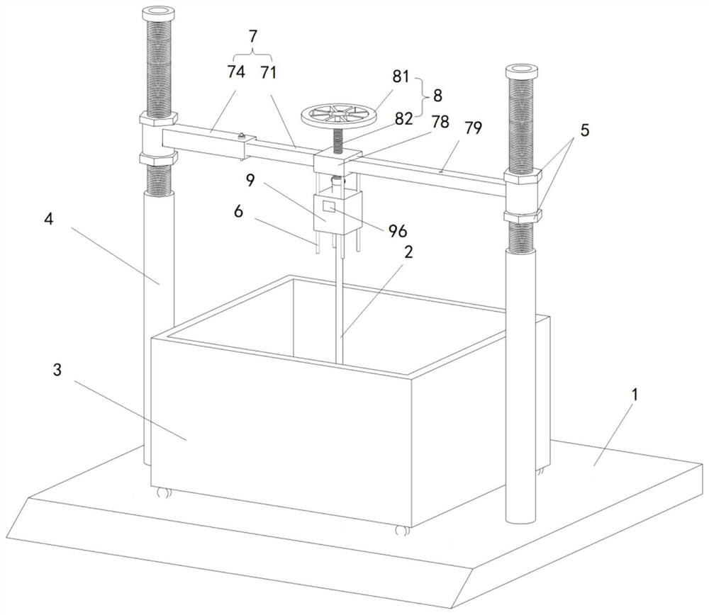
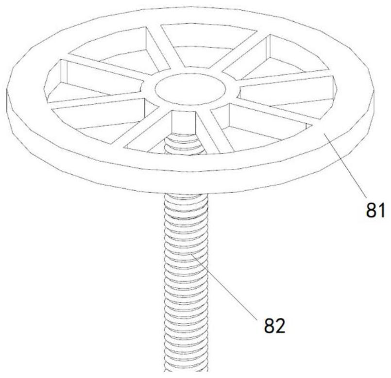
[0032] Such as figure 1 and Figure 10 As shown, the auxiliary test device includes a bracket assembly, a screw-in device, a torque sensor 9 , a plurality of limit rods 6 , a screw anchor 2 , a rotating assembly 10 , a spring dynamometer 11 , and a sandbox 3 . The bracket assembly includes a horizontal bottom plate 1, two sliding rods 4 respectively arranged at both ends of the bottom plate 1 and extending upwards, and a cross bar 7 slidably arranged on the two sliding rods 4, and the sliding rods 4 are fixed to the bottom plate 1 Connection; the screw-in device includes a hand wheel 81 and a guide rod 82 extending downward from the hand wheel 81 , and the hand wheel 81 is integrally connected with the guide rod 82 .

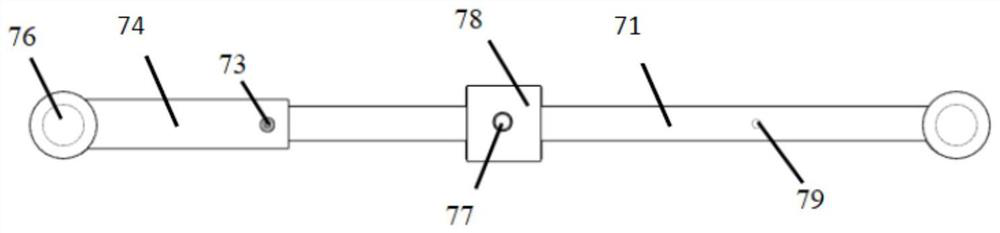
[0033] Such as Figure 2 to Figure 6 As shown, the two ends of the cross bar 7 are respectively provided with a...


PUM


Abstract

The invention provides an auxiliary test device. The auxiliary test device comprises a bracket assembly, a screw-in device, a torque sensor, a plurality of limiting rods and a spiral anchor rod, the support assembly comprises a bottom plate, two sliding rods which are arranged on the bottom plate and extend upwards, a cross rod which is arranged on the two sliding rods in a sliding mode and a sand box which is arranged on the bottom plate and contains sand, a threaded hole which vertically penetrates through the cross rod is formed in the cross rod, and a plurality of screw holes are formed in the bottom of the cross rod; the screw-in device comprises a hand wheel and a guide rod extending downwards from the hand wheel; the top of the torque sensor is provided with a limiting bayonet, the bottom of the torque sensor is provided with a fixed support, and the torque sensor is provided with a numerical value display screen and a plurality of hole channels vertically penetrating through the torque sensor; when the guide rods are in threaded fit and penetrate through the threaded holes and then are matched in the limiting bayonets, the upper ends of the limiting rods penetrate through the hole channels, then the upper ends of the limiting rods are connected to the corresponding threaded holes in a fastened mode, the upper ends of the spiral anchor rods are matched in the fixing base, the lower ends of the spiral anchor rods are located in sand in the sand box, and the numerical value display screen is used for displaying the torque value of the spiral anchor rods screwed into the sand.

Description

technical field [0001] The invention relates to the field of mechanical testing devices for building materials, in particular to an auxiliary testing device for spiral anchor rods. Background technique [0002] Spiral anchor foundations are widely used in geotechnical engineering such as power transmission line engineering, wind power generation, photovoltaic power generation, and pipeline foundations due to their advantages of quick installation, no need for excavation or curing, environmental friendliness, and construction under various climatic conditions. . During the installation process, special construction machinery is used to apply installation torque to the anchor rod, so that the screw anchor is screwed into the soil layer. Choosing an installation torque that is too high or too low may cause damage to the anchor body, failure to install, soil disturbance, etc. have a certain value. [0003] However, there are few test devices for studying the installation char...

Claims


Application Information

Patent Timeline
Patent Type & Authority Applications(China)
IPC IPC(8): E02D33/00G01L3/00
Inventor 耿志闯丁诗佳李晨楠张沛费康
Owner YANGZHOU UNIV
Why Eureka
Try Eureka