Intelligent vehicle and wheel edge driving device thereof

A wheel-side drive and smart car technology, applied in the field of smart cars, can solve the problems of reducing the quality and overall size of the wheel-side drive device, the torque and speed cannot be independently controlled, and the car body has no protection effect, etc., so as to be beneficial to the overall layout, Diversification of rich functions and power saving effect

Inactive Publication Date: 2022-04-01
YANCHENG INST OF TECH +1
View PDF0 Cites 1 Cited by
  • Summary
  • Abstract
  • Description
  • Claims
  • Application Information

AI Technical Summary

Problems solved by technology

[0005] The purpose of the present invention is to provide a smart car and its wheel drive device, to solve the problem that most of the existing smart cars proposed in the above background technology do not have a four-wheel drive and four-rotation drive system, which makes the rotation of each wheel The torque and speed cannot be controlled independently, which increases the power consumption of the battery. At the same time, the existing drive system is too complicated, and the wheelbase is too long, so it is impossible to reduce the wheel drive device under the premise of ensuring power, economy and smoothness. The quality and overall size increase the production cost. At the same time, the car body itself does not have a good anti-collision structure, which does not have a good protective effect on the car body.

Method used


Image

  • Intelligent vehicle and wheel edge driving device thereof
  • Intelligent vehicle and wheel edge driving device thereof
  • Intelligent vehicle and wheel edge driving device thereof

Examples


Embodiment 1

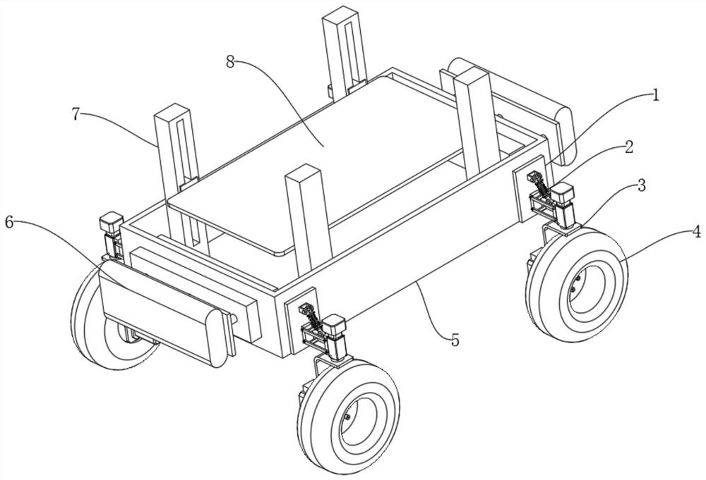
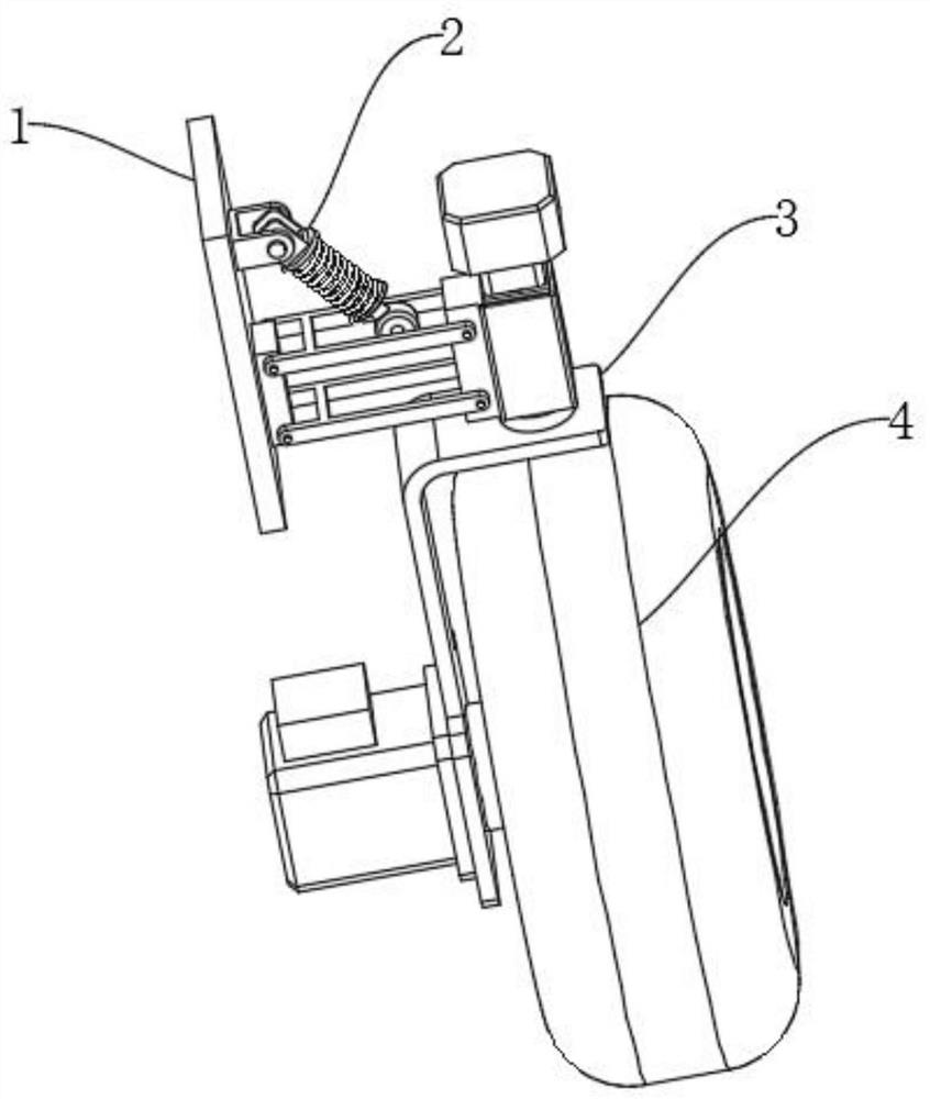
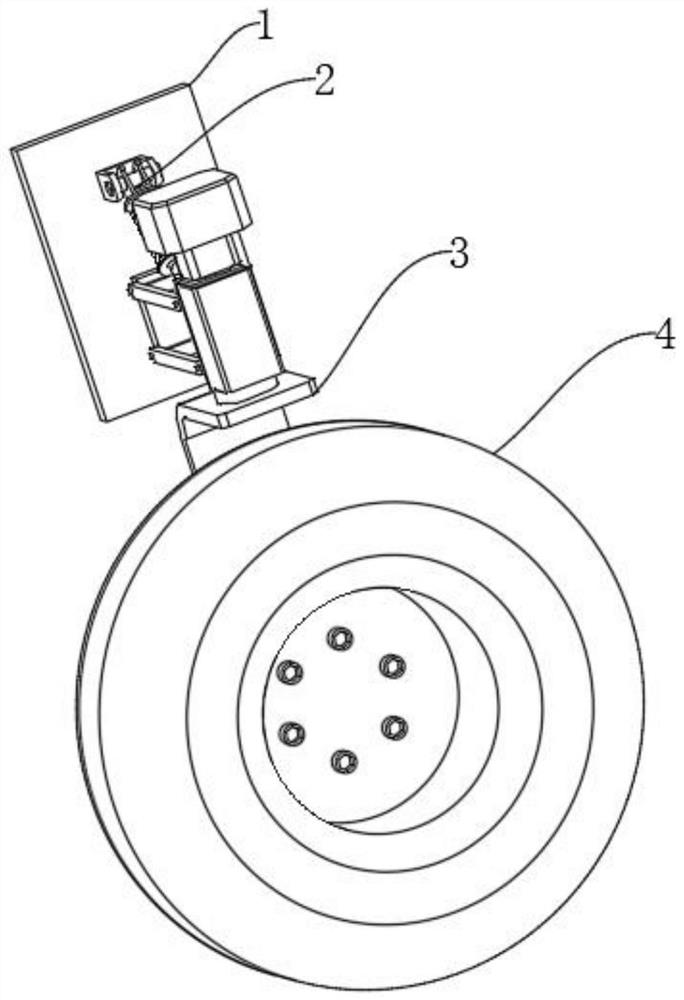
[0054] Example 1: See Figure 1-10 , a wheel edge driving device, comprising a mounting plate 1, the outer side of the mounting plate 1 is fixedly connected with a shock absorbing mechanism 2, the lower end of the shock absorbing mechanism 2 is provided with a driving mechanism 3, and the output end of the driving mechanism 3 is equipped with a wheel 4;

[0055] see Figure 1-10 , a wheel drive device also includes a shock absorber 2, the shock absorber 2 includes a first connecting block 21, a second connecting block 22, a first support frame 23, a second support frame 24, a shock absorber 25, a first The mounting base 26 and the rotating motor 27, the first connecting block 21 and the second connecting block 22 are all fixedly installed on the outside of the mounting plate 1, and the outside of the second connecting block 22 is provided with a first support frame 23 and a second support frame 24, A shock absorber 25 is arranged between the second support frame 24 and the fi...

Embodiment 2

[0058] Embodiment 2: as Figure 4 , Figure 5 , Figure 6 As shown, the drive mechanism 3 includes a support 31, a servo motor 32, a servo driver 33, and a wheel mounting seat 34. The support 31 is installed on the output end of the rotating motor 27, and the servo motor 32 and the wheel mounting seat 34 are oppositely installed on the support 31. 4. Installed on the wheel mount 34, the output shaft of the servo motor 32 passes through the bracket 31 and is connected with the wheel mount 34, and the servo driver 33 is installed on the servo motor 32;

[0059] The wheel mount 34 includes:

[0060] The fixed ring seat 35 is fixedly connected to the bracket 31;

[0061] An annular groove 36, the annular groove 36 is opened on the end of the fixed ring seat 35 away from the bracket 31;

[0062] The oil groove 37 is set on the inner ring of the fixed ring seat 35 in the circumferential direction;

[0063] The conductive coil cover 38, the conductive coil cover 38 is rotatably ...

Embodiment 3

[0082] Example 3: See Figure 1-10 , a kind of intelligent car, comprises a kind of wheel edge drive device as above, also comprises vehicle body 5, and the outer side of vehicle body 5 is fixedly connected with buffering mechanism 6, and the interior of vehicle body 5 is fixedly connected with lifting mechanism 7, is provided with between lifting mechanism 7 carrier board 8;

[0083] The buffer mechanism 6 includes a second mounting seat 61, a cavity 62, a moving rod 63, a connecting plate 64, an air cushion 65 and a spring 66, and the inside of the second mounting seat 61 is provided with a cavity 62, and the inside of the cavity 62 is provided with a moving rod 63, the outer side of the moving rod 63 is fixedly connected with a connecting plate 64, the outer side of the connecting plate 64 is fixedly connected with an air cushion 65, and the outer side of the moving rod 63 is located inside the cavity 62 to be provided with a spring 66;

[0084] There are two buffer mechan...


PUM


Abstract

The invention discloses an intelligent vehicle and a wheel edge driving device thereof, and relates to the technical field of intelligent vehicles, the intelligent vehicle comprises a mounting plate, the outer side of the mounting plate is fixedly connected with a damping mechanism, the lower end of the damping mechanism is provided with a driving mechanism, and the output end of the driving mechanism is provided with wheels. The invention provides the damping mechanism, the driving mechanism, the lifting mechanism and the damping mechanism, the driving system of the intelligent vehicle is designed into the four-wheel-drive four-rotation intelligent vehicle adopting the wheel-side motor device as the driving system, the wheel-side driving system is simple in structure and convenient to produce and manufacture, the wheel base of the whole wheel-side driving device is shortened through the design, and the service life of the whole wheel-side driving device is prolonged. The weight and the overall size of the wheel edge driving device are reduced on the premise that the dynamic property, the economical efficiency and the smoothness are guaranteed, meanwhile, the buffering mechanisms are additionally arranged at the front end and the rear end of the vehicle body, the buffering protection effect is achieved, equipment and devices of an intelligent vehicle can be placed on the carrying plate, and the height is controlled and adjusted through the lifting mechanism.

Description

technical field [0001] The invention relates to the technical field of smart cars, in particular to a smart car and a wheel-side driving device thereof. Background technique [0002] A smart car is the product of the combination of the latest scientific and technological achievements such as electronic computers and the modern automobile industry, so it is "understanding", and usually has the functions of automatic driving, automatic speed change, and even automatic road recognition. In addition, all kinds of auxiliary facilities in the car should also be computerized, which often gives people a sense of novelty. [0003] Wheel drive, also known as all-wheel drive, means that the front and rear wheels of the car have power, which is generally represented by four times four. The driving forms of the car generally have the following types, front rear drive, front front drive, rear rear drive , mid-mounted rear drive, four-wheel drive, the so-called driving form refers to the ...

Claims


Application Information

Patent Timeline
IPC IPC(8): B60K7/00B60G13/00B60R19/18F16F15/023F16F15/04F16F15/06
Inventor 刘玮俞跃于水胜王啸威
Owner YANCHENG INST OF TECH
Why Eureka
Try Eureka