
Method for electrical coupling of battery cells of battery module, and battery module

An electrical coupling, battery module technology, applied in electrical components, battery pack components, circuits, etc., can solve the problems of reducing heat dissipation power loss on electrical contact surfaces, reducing manufacturing costs, increasing electrical contact surfaces, and simplifying device effect

Pending Publication Date: 2022-03-15
VOLKSWAGEN AG
View PDF1 Cites 0 Cited by
  • Summary
  • Abstract
  • Description
  • Claims
  • Application Information

AI Technical Summary

Problems solved by technology

However, such a battery module has the disadvantage that the individual individual components to be electrically coupled to each other must be manufactured and oriented to each other particularly precisely.
Small positional and tolerance deviations of the components can already lead to a reduction in the electrical contact area and thus to an increase in the contact resistance and the associated higher heat dissipation and increased power loss during charging of the battery cells

Method used


Image

  • Method for electrical coupling of battery cells of battery module, and battery module
  • Method for electrical coupling of battery cells of battery module, and battery module
  • Method for electrical coupling of battery cells of battery module, and battery module

Examples


Embodiment Construction

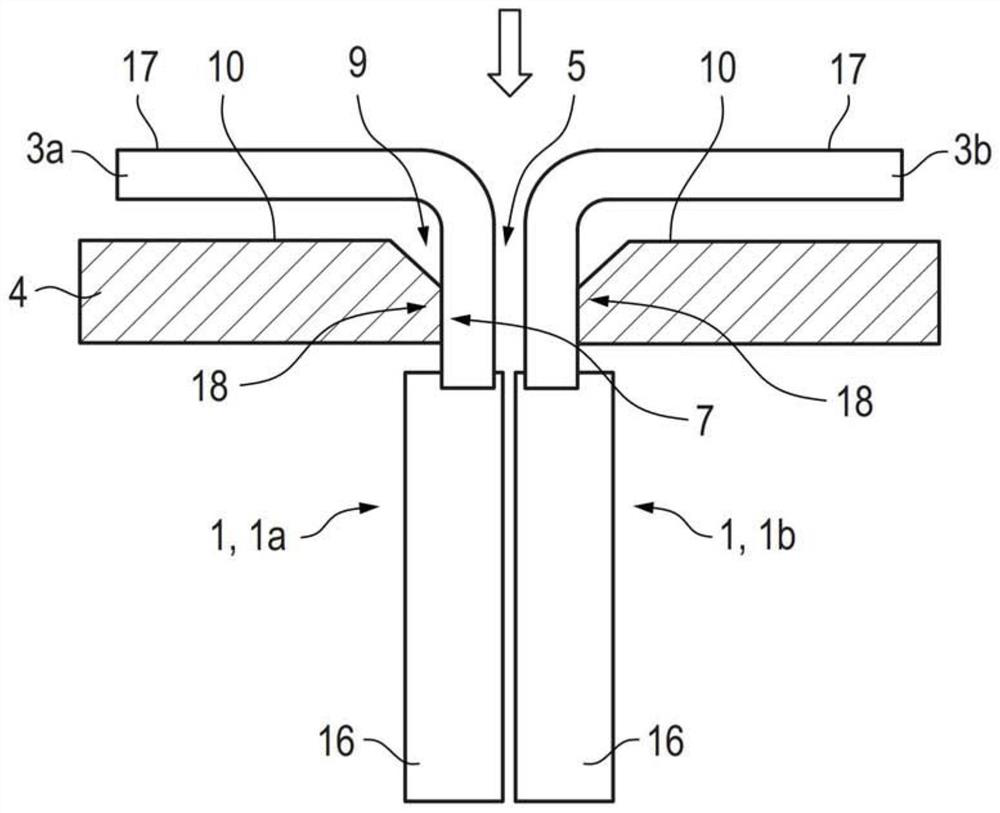
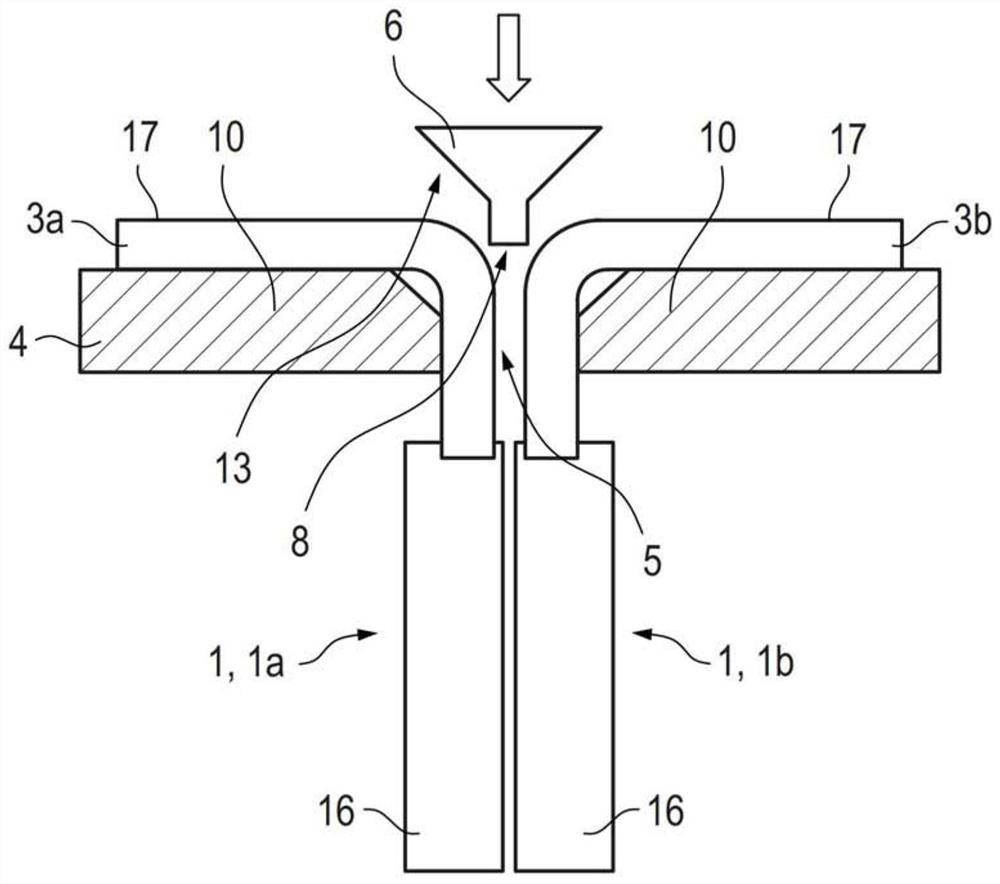
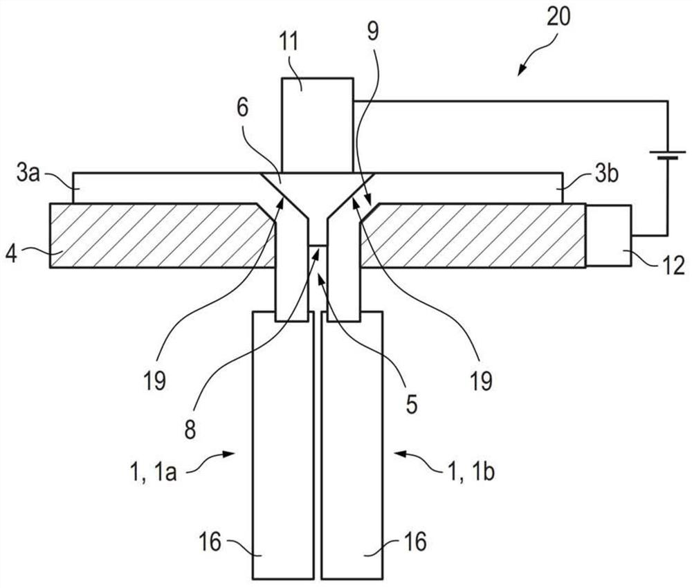
[0039] exist figure 1 A first state during the implementation of a preferred embodiment of the method according to the invention is shown schematically in a side view. In the first state, the two battery cells 1 , namely the first battery cell 1 a and the second battery cell 1 b are arranged on the conductor rail 4 in such a way that the first cell lugs 3 a of the first battery cell 1 a are and the second cell tabs 3b of the second battery cell 1b protrude through the perforations 5 of the conductor busbar 4 . Furthermore, the battery cells 1 each have active components 16 , wherein the active components 16 are all arranged on the same side of the conductor rail 4 . The first cell tab 3a and the second cell tab 3b each have a first end region 17 pointing away from the active component 16 and a second end region 18 leading into the active component 16, wherein the The one end region 17 and the second end region 18 are basically arranged on different sides of the conductor rai...


PUM


Abstract

The invention relates to a method for producing an electrical coupling of battery cells (1) of a battery module (2), comprising the following steps: providing a first battery cell (1a) having a first cell tab (3a) and a second battery cell (1b) having a second cell tab (3b), providing a conductor busbar (4) having a through-hole (5), providing a connecting element (6), arranging a first cell tab (3a) and a second cell tab (3b) on the perforation (5); -moving the connecting element (6) between the first cell tab (3a) and the second cell tab (3b) close to the through-hole (5) and-integrally connecting the first cell tab (3a) and the second cell tab (3b) to the conductor busbar (4) in the region of the through-hole (5) and to the connecting element (6) by resistance welding. The invention further relates to a battery module (2) produced by means of the method according to the invention.

Description

technical field [0001] The invention relates to a method for establishing electrical coupling of battery cells of a battery module. The invention also relates to a battery module having a plurality of battery cells that are electrically coupled to each other. Background technique [0002] Battery modules are known in which a plurality of battery cells are electrically coupled or connected to one another. The electrical coupling of the battery cells takes place via so-called cell tabs, which are made of electrically conductive material and lead out of the battery cells. The individual cell tabs are electrically coupled to each other by connecting means, for example by busbars or busbars, "printed circuit boards" also known as "PCBs", or the like. In the context of the present invention, such connecting means are collectively referred to as "conductor busbars". [0003] In a common connection, the cell tabs of adjacent battery cells are guided through perforations in the co...

Claims


Application Information

Patent Timeline
Patent Type & Authority Applications(China)
IPC IPC(8): H01M50/503H01M50/531H01M50/519
CPCH01M50/503H01M50/531H01M50/519H01M50/516Y02E60/10
Inventor O.米希尔M.克林克A.哈姆斯D.劳特巴赫N.伊斯拉米
Owner VOLKSWAGEN AG
Learn More