Drawing device for architectural design

A technology for architectural design and placement of slots, applied in computing, instruments, printing, etc., can solve problems such as poor line scanning effects, and achieve accurate outlines, good effects, and easy adjustments

Pending Publication Date: 2022-03-15
刘君
View PDF1 Cites 0 Cited by
  • Summary
  • Abstract
  • Description
  • Claims
  • Application Information

AI Technical Summary

Problems solved by technology

The drawing board has a working part and a display part. The working part of the drawing board can be used for manual drawing. The display part of the drawing board is equipped with an electronic display. When the drawing is completed, the scanned drawing can be displayed on the electronic display through the scanner. It is convenient for the preservation and display of drawings, and it is convenient for designers to use, but this design can only be scanned electronically, and the scanning effect is not good for lines with large vertical contours

Method used


Image

  • Drawing device for architectural design
  • Drawing device for architectural design
  • Drawing device for architectural design

Examples


Embodiment

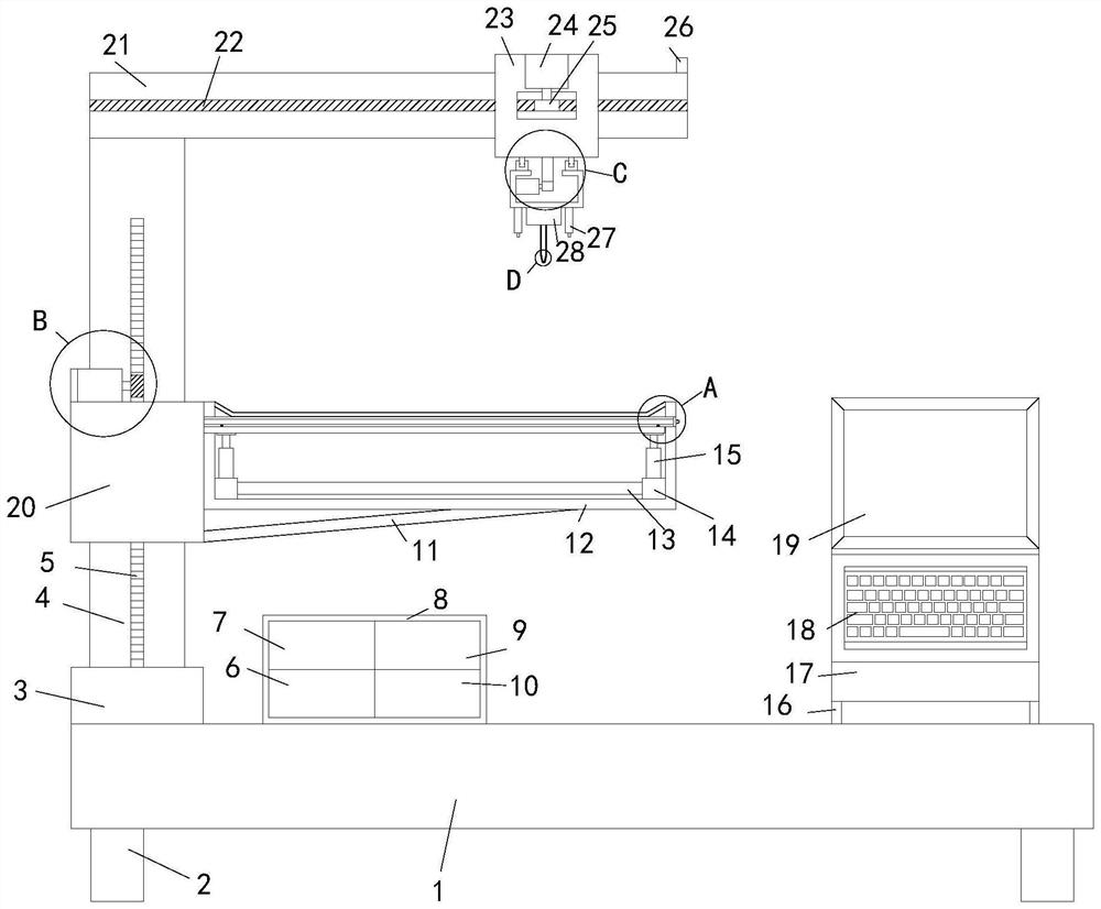
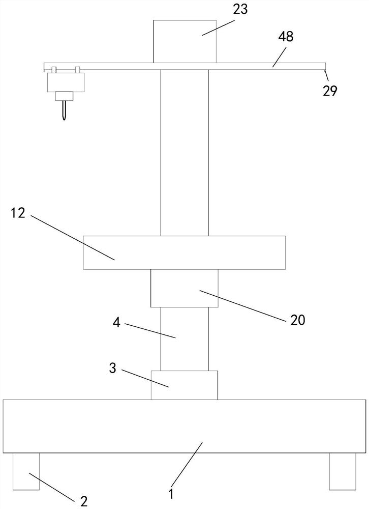
[0031] see Figure 1-6, a drawing device for architectural design, comprising a chassis 1, a control box 8 is arranged on the top of the chassis 1, and a first chamber is arranged in the control box 8, and a power supply 6 and a light sensor are arranged on the inner bottom wall of the control box 8 10, the top of the power supply 6 and the top of the light sensor 10 are respectively provided with a host computer 7 and an image generator 9, and the left side of the top of the chassis 1 is provided with a shaft sleeve 3, and the inner wall of the shaft sleeve 3 is sleeved with a pillar 4, The front end of the pillar 4 is provided with a groove one, and the inside of the groove one is provided with a rack one 5, the circumference outer wall of the pillar 4 is covered with a shaft sleeve two 20, and the left side of the top end of the shaft sleeve two 20 is provided with a fixed plate 39 for fixing The right end of plate 39 is provided with motor two 40, and the output end of mot...


PUM


Abstract

The invention relates to the technical field of buildings, in particular to an architectural design tracing device which comprises a base plate, a control box is arranged at the top end of the base plate, a first cavity is formed in the control box, a power source and a light sensor are arranged on the inner bottom wall of the control box, and the circumferential outer wall of a supporting column is sleeved with a second shaft sleeve. A second motor is arranged at the right end of the fixing plate, a second gear is arranged at the output end of the second motor, a workbench is arranged at the right end of the second shaft sleeve, connecting blocks are arranged on the left side and the right side of the inner bottom wall of the workbench, and a display screen is arranged in the upper area of the front end of the control frame. A keyboard input unit is arranged at the bottom end of the display screen, a cross beam is arranged at the top end of the supporting column, a second rack is arranged at the front end of the cross beam, a third shaft sleeve sleeves the outer wall of the circumference of the cross beam, and a third rack is arranged in the middle of the bottom end of the third shaft sleeve, so that electric tracing is achieved, electronic pictures can be formed, and practicability is high.

Description

technical field [0001] The invention relates to the technical field of architecture, in particular to a drawing device for architectural design. Background technique [0002] As we all know, tracing is to draw according to the original drawing, cover the original drawing with relatively transparent paper, draw the drawing with a pen, and then stick the thin paper on a relatively thick cardboard. The original meaning of tracing is Cover the original drawing with transparent or translucent paper, and use a drawing instrument to draw ink lines according to the pattern. It is similar to rubbing, except that the final effect still needs to be traced by yourself bit by bit. Tracing can basically restore the frame structure and design ideas of the original drawing, and can be recolored and recreated on the basis of it. [0003] Most of the current drawings are drawn by hand, and cannot be formed into an electronic version. Instead, they are uploaded to the computer through scanned...

Claims


Application Information

Patent Timeline
IPC IPC(8): B43L13/00G06F3/0354G06F3/041
CPCB43L13/00G06F3/041G06F3/03545
Inventor 刘君
Owner 刘君
Why Eureka
Try Eureka