
Hair dryer

A hair dryer, first fluid technology, applied in hairdressing equipment, hair drying devices, devices for washing hair or scalp, etc., can solve the problems of inability to eliminate pressure loss and noise, pressure loss, turbulence, etc. The effect of smooth flow path, stable flow rate, elimination of pressure loss and noise problems

Pending Publication Date: 2022-03-04
最火科技(杭州)有限公司
View PDF2 Cites 0 Cited by
  • Summary
  • Abstract
  • Description
  • Claims
  • Application Information

AI Technical Summary

Problems solved by technology

[0004] The above technique suffers from the following disadvantages: the fan unit draws fluid through the primary fluid inlet towards the body through the primary fluid flow path that extends from the primary fluid inlet and enters the body where the handle and body engage; Because the switch assembly is set on the inner wall of the handle, when the fluid passes in the main fluid flow path, this causes turbulence to the fluid flow, and its switch assembly produces pressure loss and noise; although the switch assembly, made such as "upstream end The portion 110a bends away from the inner surface 220a of the inner wall 220, providing an improvement of the gradually decreasing cross-sectional area "of the main fluid flow path 400, but it is only reduced, and cannot eliminate pressure loss and noise; and, in the fluid In the process of being sucked into the fan unit by the fan unit, the wall of the motor also has an effect

Method used


Image

  • Hair dryer
  • Hair dryer

Examples


Embodiment Construction

[0021] The present invention will be further described below in conjunction with the accompanying drawings and specific embodiments. Those skilled in the art will be able to implement the present invention based on these descriptions. In addition, the embodiments of the present invention referred to in the following description are generally only some embodiments of the present invention, not all of them. Therefore, based on the embodiments of the present invention, all other embodiments obtained by persons of ordinary skill in the art without creative efforts shall fall within the protection scope of the present invention.

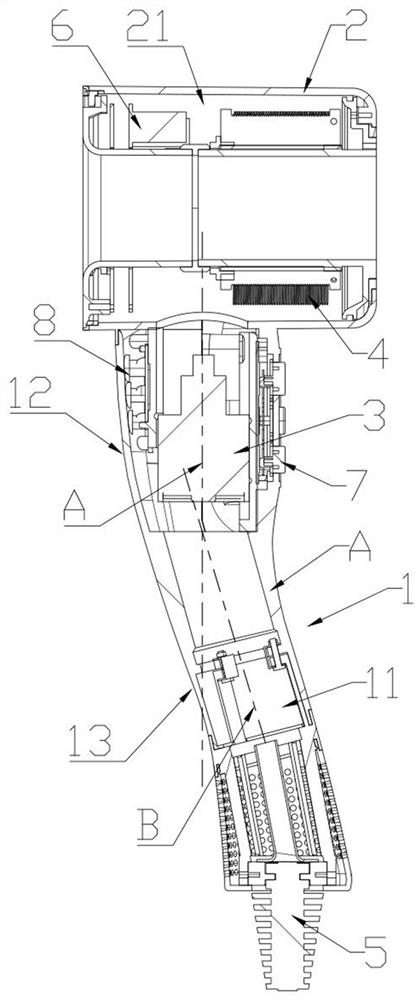
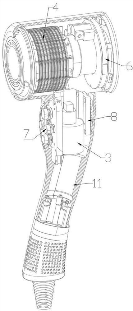
[0022] Such as figure 1 and figure 2 As shown, the hair dryer includes a handle 1 and a blower 2 . The upper end of the handle 1 is connected to the air cylinder 2, and the middle of the handle 1 is hollow. Inside the handle 1, a first fluid flow path 11 is formed from the lower end to the upper end of the handle 1. The air cylinder 2 has an inner wal...


PUM


Abstract

A hair dryer comprises a handle and a fan assembly, a first fluid flowing path, a handle handheld portion and a ventilation portion are formed in the handle from the lower end to the upper end of the handle, the fan assembly is arranged in the handheld portion and located at the position, close to the ventilation portion, of the handheld portion, and the first fluid flowing path corresponds to the handheld portion and the ventilation portion. The two sections comprise a handheld section and a ventilation section, the diameter of the handheld section is larger than that of the ventilation section, and the handheld section is locally expanded on the two sides of the fan assembly. After the motor is arranged on the handheld part section, in the process that fluid is sucked by the fan assembly to enter the fan assembly, the fluid enters the motor from the handheld part section smaller than or equal to the inner diameter of the motor, so that the wall of the motor does not influence fluid suction, and the handheld part section is expanded outwards to accommodate and install the switch assembly and the lamp indication PCB. Therefore, fluid is not in contact with the components, and the problems of pressure loss and noise generated by a switch assembly in the prior art are solved.

Description

technical field [0001] A hair dryer of the invention relates to the field of hair care appliances. Background technique [0002] Typically, hair dryers include a motor and a fan that draw fluid into the body; the fluid may be heated before leaving the body. The motor is prone to damage from foreign objects such as dirt or hair, so a filter is usually provided at the fluid inlet of the hair dryer. Fans and heaters require electricity to function and this is provided by internal wiring from the mains power cable or batteries attached to the appliance. [0003] There are some disadvantages in existing hair dryers where motors and switches are installed in the handle. For example, the Chinese patent with the publication number CN201610344407.5 discloses a handheld appliance whose fan unit is arranged downstream of the main fluid inlet; the control button The switch assemblies form part of the inner wall of the handle via indirect engagement with their switches. The switch cov...

Claims


Application Information

Patent Timeline
Patent Type & Authority Applications(China)
IPC IPC(8): A45D20/10A45D20/12
CPCA45D20/10A45D20/122A45D20/12
Inventor 叶军忠刘玉军
Owner 最火科技(杭州)有限公司
Learn More