


Quick Research
Generate reliable direction feasibility study reports for your R&D in just a few steps.

Technical Q&A
Discover and master advanced knowledge NOW. Basics, ideas, possibilities, all at once.

Find Solutions
As an expert in R&D theories, this can generate solutions to your technical problems instantly.

Evaluate Feasibility
Analyze your overall solution with one click, know your potential R&D risks in advance.

Monitor Landscape
Get weekly tech updates, stay abreast of the latest tech innovations and key insights.
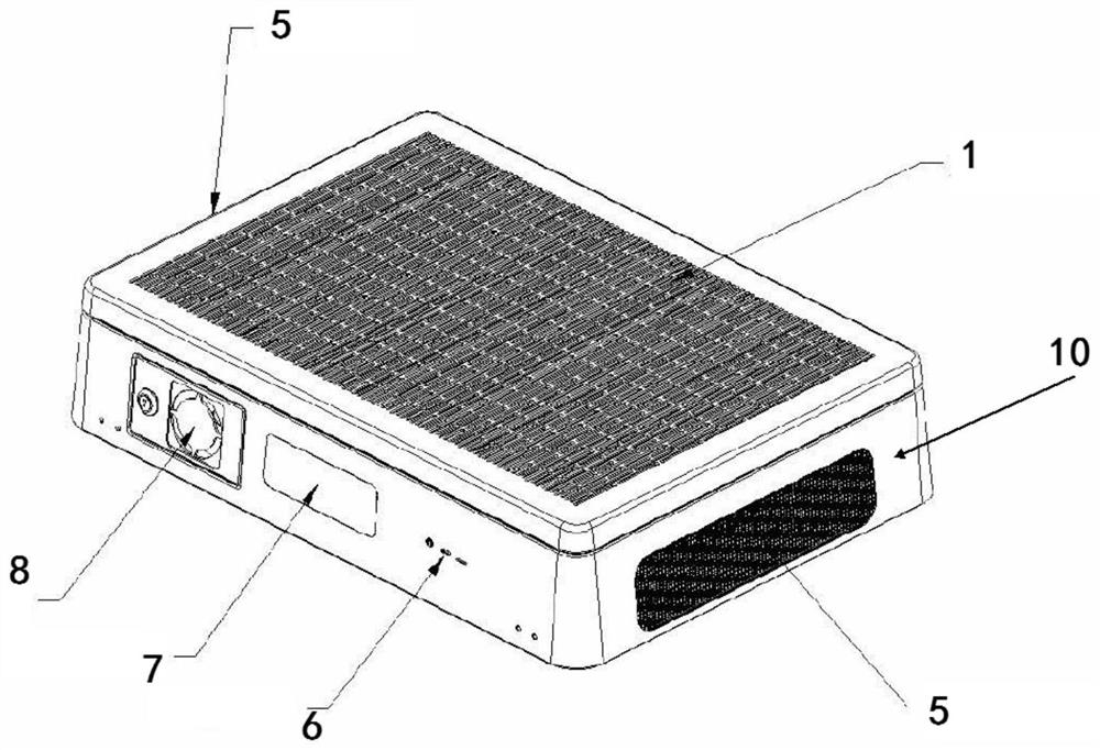
Method for monitoring service life of filter element of air purifier
A technology of air purifier and filter element life, applied in the field of air purification
- Summary
- Abstract
- Description
- Claims
- Application Information
AI Technical Summary
Problems solved by technology
Method used
Image

Examples
Embodiment 1
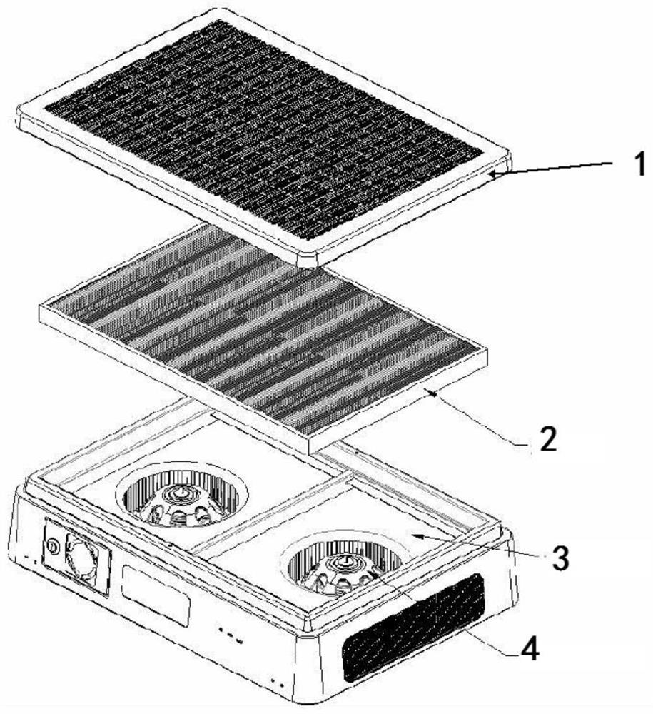
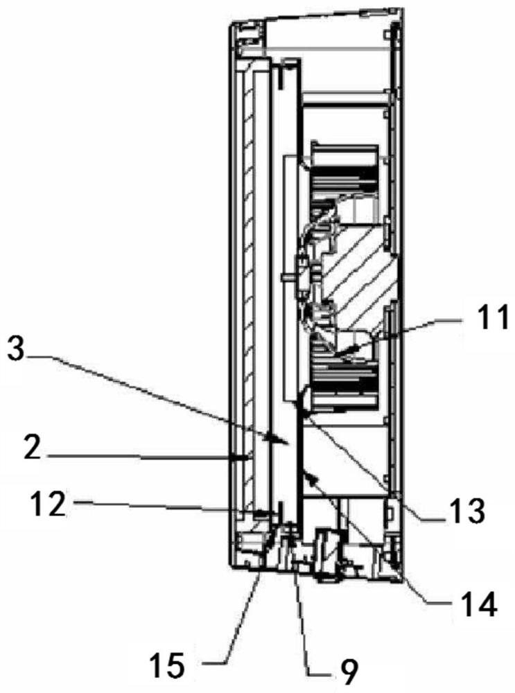
[0084] Such as image 3 As shown, the light source 9 is placed on the side wall 15 of the air intake cabin 3 . A light baffle 12 is arranged on the side of the light source 9 passing through the filter core 2 to prevent the light emitted by the light source 9 from leaking from the side and prevent the light emitted by the light source 9 from directly passing through the filter core 2 to exit. The light blocking plate 12 is arranged in a direction perpendicular to the light from the light source, so as to prevent the light emitted by the light source 9 from directly passing through the filter core 2 to exit. The side of the light baffle plate 12 close to the light source 9 has a reflective surface, which is used to reflect and irradiate light into the wind inlet compartment 3 . A reflective surface 14 may be provided on the side facing the filter element 2 in the wind inlet compartment 3 for uniformly reflecting light onto the filter element 2 . A light baffle 13 is arranged ...
Embodiment 2
[0089] Such as Figure 5 As shown, the light source 9 is arranged on the side facing the filter element 2 in the air inlet cabin 3 . The light source 9 is a strip light source. A light baffle 13 can be arranged on the circumference of the wind wheel 11 to prevent the light source from overflowing from the air outlet 5 through the air inlet of the wind wheel, causing light interference and affecting the user's judgment of the brightness of the light source at the air inlet surface (cover plate 1). Such as Figure 6 As shown, the light source 9 is covered with a light source optimizer 16 to ensure that the light emitted through the filter element 2 is more uniform through the refraction and reflection of the light source.
[0090] According to the above measurement method (wherein, the color temperature of the light source is SMT-LED 3.0*3.0 positive white light 6500K, and the illuminance meter is placed at a distance of 1 meter directly below the light source), the curve valu...
Embodiment 3
[0093] Such as Figure 7 As shown, the light source 9 is arranged on the side facing the filter core 2 in the air inlet cabin 3; meanwhile, the light source 9 is also located on the back side of the reflective surface 14, has a certain distance from the reflective surface 14, and faces the direction of the filter core 2. The light passes through the reflective surface 14 towards the direction of the filter core 2, and the reflection effect of the reflective surface 14 ensures that the light transmitted through the filter core 2 is uniform. The light source 9 is covered with a light source optimizer 16, which ensures that the light transmitted through the filter core 2 is more uniform through the refraction and reflection of the light source. A light baffle 13 can be arranged on the circumference of the wind wheel 11 to prevent the light source from overflowing from the air outlet 5 through the air inlet of the wind wheel, causing light interference and affecting the user's jud...
PUM
 Abstract
Description
Claims
Application Information
 - R&D Engineer
- R&D Manager
- IP Professional
- Industry Leading Data Capabilities
- Powerful AI technology
- Patent DNA Extraction
Browse by: Latest US Patents, China's latest patents, Technical Efficacy Thesaurus, Application Domain, Technology Topic, Popular Technical Reports.
© 2024 PatSnap. All rights reserved.Legal|Privacy policy|Modern Slavery Act Transparency Statement|Sitemap|About US| Contact US: help@patsnap.com