Bottle cap assembly

A technology of bottle caps and components, applied in the field of medical inspection, can solve problems such as instability, complex claw structure, and low efficiency

Pending Publication Date: 2022-02-01
泰普生物科学(中国)有限公司
View PDF1 Cites 0 Cited by
  • Summary
  • Abstract
  • Description
  • Claims
  • Application Information

AI Technical Summary

Problems solved by technology

Due to its low efficiency and high risk of biological contamination, manual unscrewing and closing of bottle caps cannot meet the needs of huge inspection workloads in medical hospitals, and the application of automated bottle cap opening and closing on medical inspection equipment is becoming more and more more and more
[0003] See the utility model patent CN213923979U, which discloses "a rotary head for protecting the anti-slip pattern of the plastic cap". The friction provided by the thread is not stable, and it is prone to the problem of under-tightening and over-tightening
As a result, in the opening and closing debugging process of the actual bottle cap, it is necessary to control the degree of clamping of the bottle cap by the rotary head, the debugging time is long, it is not stable, and the after-sales maintenance pressure is high
At the same time, the peripheral diameter of the claw-type rotary head is larger than the diameter of the bottle cap, and the volume is relatively large, which cannot meet the requirements of equipment miniaturization, and the structure of the claws is relatively complicated, and the production cost is high.

Method used


Image

  • Bottle cap assembly
  • Bottle cap assembly
  • Bottle cap assembly

Examples


Embodiment 1

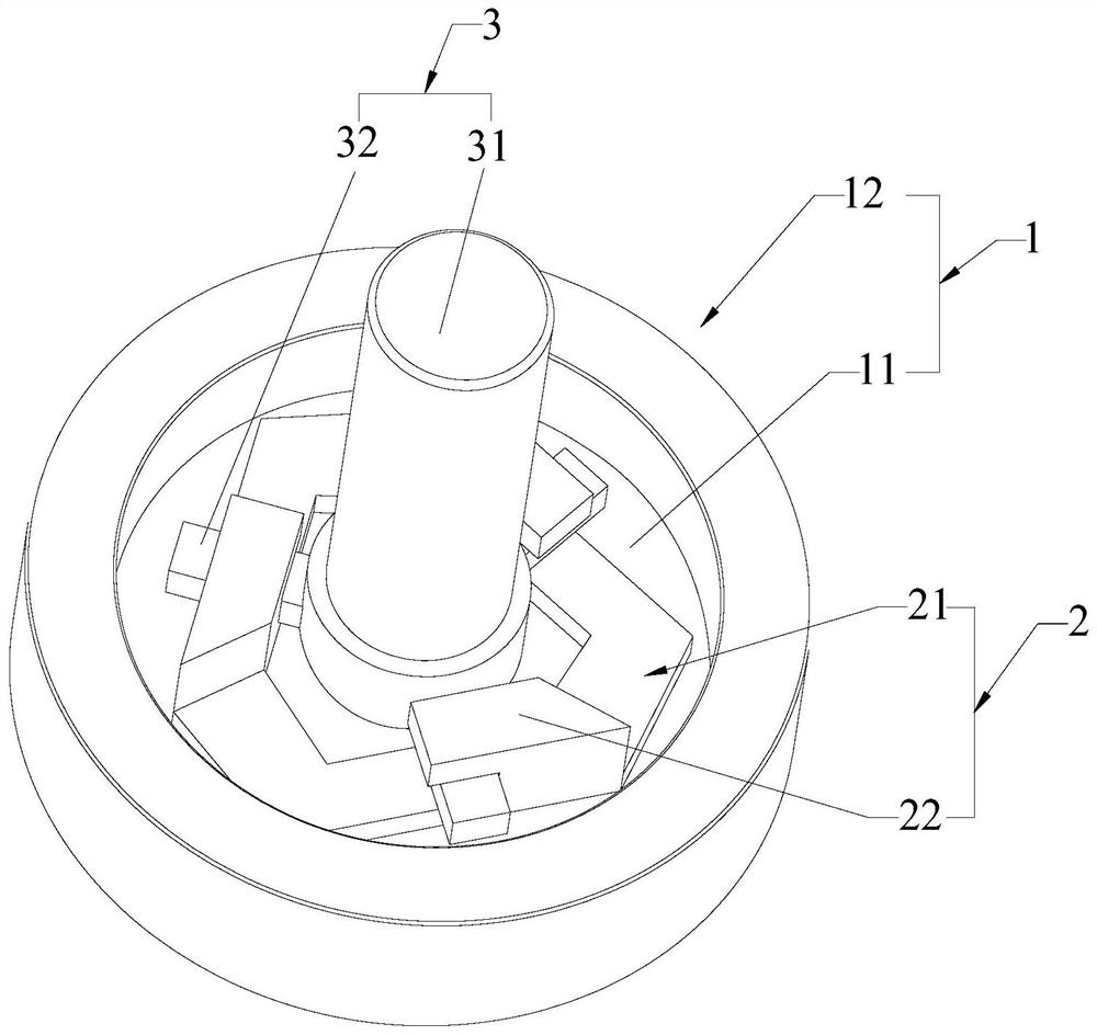
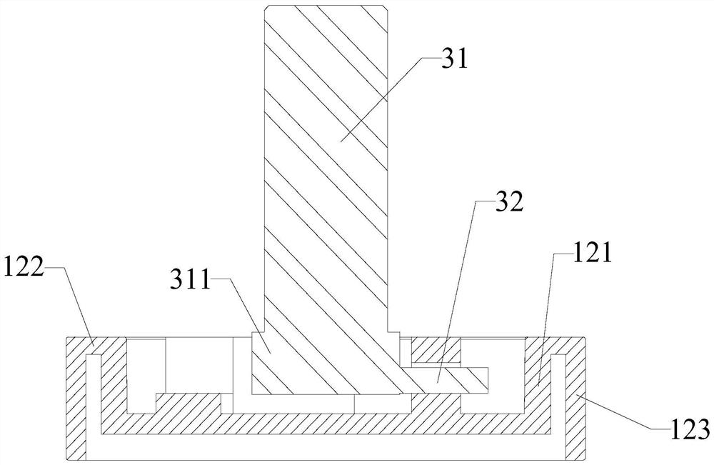
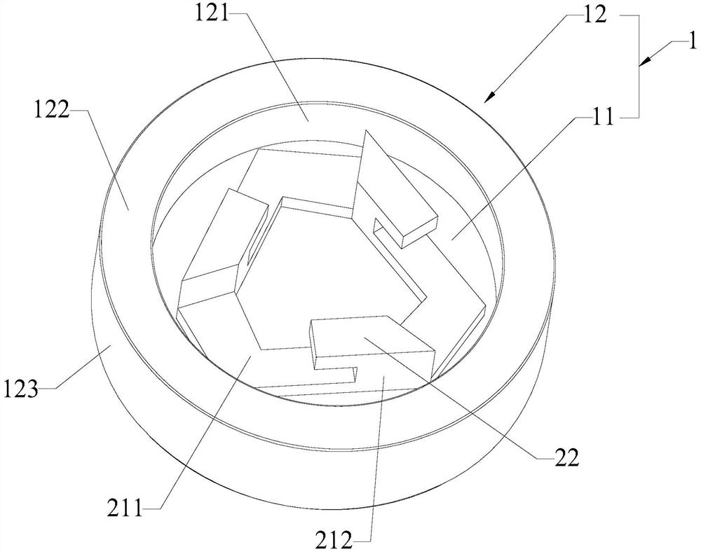
[0041] Please refer to Figure 1 to Figure 3 As shown, a bottle cap assembly includes a bottle cap 1, a push assembly 2 and a screw head 3, the bottle cap 1 includes a base 11 and a threaded portion 12, and the threaded portion 12 is circumferentially arranged on the edge of the base 11, so The threaded part 12 is used for threading the bottle cap 1 on the reagent bottle; the push assembly 2 includes a transmission frame 21 and a hanging plate 22, and the transmission frame 21 is arranged on the top surface of the base 11 around the center line of rotation of the bottle cap 1 Above, the transmission frame 21 encloses an area for placing the rotary head 3 to rotate, and the hanging plate 22 is provided on the top of the transmission frame 21, and the hanging plate 22 is used for the bottle cap 1 to be suspended on the rotary head 3; The rotary head 3 rotates in the area to drive the rotation of the bottle cap 1 .

[0042] The transmission frame 21 includes a guide plate 211 an...


PUM


Abstract

The invention discloses a bottle cap assembly. The bottle cap assembly comprises a bottle cap, a pushing assembly and a rotating head, the bottle cap comprises a base and a threaded part, the threaded part is circumferentially arranged on the edge of the base, and the threaded part is used for threaded connection of the bottle cap to a reagent bottle; the pushing assembly comprises a transmission frame and a hanging plate, the transmission frame is arranged on the top face of the base around the rotating center line of the bottle cap, an area used for containing the rotating head to rotate is defined by the transmission frame, and the hanging plate is arranged at the top of the transmission frame and used for hanging the bottle cap on the rotating head; and the rotating head rotates in the area so as to drive the bottle cap to rotate. The threaded part and the pushing assembly are additionally arranged on the bottle cap, then the rotating head rotates in the area defined by the transmission frame of the pushing assembly, and then the rotating head drives the bottle cap to correspondingly rotate through the transmission frame, so that the threaded connection relation between the threaded part and the bottle opening of the reagent bottle is changed. Meanwhile, the bottle cap can be hung on the rotating head through the hanging plate, so that the purpose of effectively sealing and opening the reagent bottle is achieved.

Description

technical field [0001] The invention relates to the technical field of medical inspection, in particular to a bottle cap assembly. Background technique [0002] During the medical inspection process, the inspector needs to unscrew the bottle cap of the medical bottle, and then perform the action of sampling or adding liquid, and then close the bottle cap. Due to its low efficiency and high risk of biological contamination, manual unscrewing and closing of bottle caps cannot meet the needs of huge inspection workloads in medical hospitals, and the application of automated bottle cap opening and closing on medical inspection equipment is becoming more and more more and more. [0003] See the utility model patent CN213923979U, which discloses "a rotary head for protecting the anti-slip pattern of the plastic cap". The friction provided by the thread is not stable, and it is prone to problems of under-tightening and over-tightening. As a result, in the opening and closing deb...

Claims


Application Information

Patent Timeline
Patent Type & Authority Applications(China)
IPC IPC(8): B65D41/04B65D41/08
CPCB65D41/0485B65D41/08
Inventor 王成鹏江峰林志耿林旺源
Owner 泰普生物科学(中国)有限公司
Why Eureka
Try Eureka