Stepless speed regulation reciprocating piston compressor suitable for new energy automobile

A new energy vehicle, stepless speed regulation technology, applied in the direction of liquid variable capacity machinery, mechanical equipment, variable capacity pump components, etc. Simple, easy-to-use effects

Active Publication Date: 2022-01-11
NANJING COLLEGE OF INFORMATION TECH
View PDF6 Cites 0 Cited by
  • Summary
  • Abstract
  • Description
  • Claims
  • Application Information

AI Technical Summary

Problems solved by technology

The existing plug compressor is directly driven by the motor when working, which cannot meet the operation of the car under different working conditions, and cannot adjust the operating power of the compressor

Method used


Image

  • Stepless speed regulation reciprocating piston compressor suitable for new energy automobile
  • Stepless speed regulation reciprocating piston compressor suitable for new energy automobile
  • Stepless speed regulation reciprocating piston compressor suitable for new energy automobile

Examples


Embodiment 1

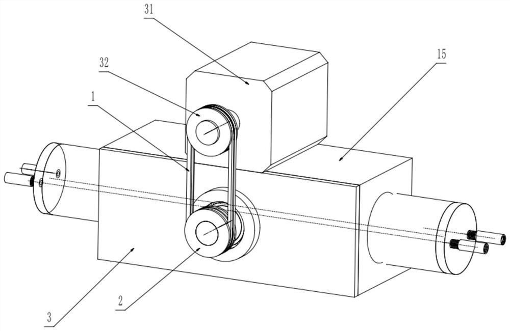
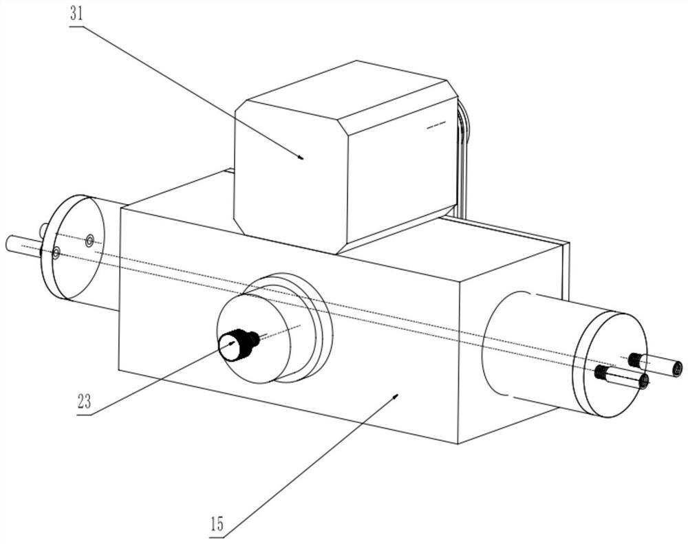
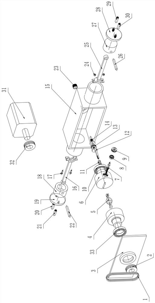
[0042] like Figure 1-6 As shown, this embodiment provides a steplessly speed-adjustable reciprocating piston compressor suitable for new energy vehicles, including a cylinder block, a drive shaft 4, a driven shaft 6, a compression mechanism and a speed regulating mechanism; the drive shaft 4 and the driven shaft The moving shaft 6 is coaxially installed on both sides of the cylinder body; the compression mechanism includes a crankshaft 5, a first connecting rod 16 and a second connecting rod 25, and the two ends of the crankshaft 5 are respectively installed in the drive shaft 4 and the driven shaft 6, and the second One end of a connecting rod 16 is installed on the crankshaft 5 surface, and the other end is connected with the first piston 18 by the first pin 22, and one end of the second connecting rod 25 is installed on the crankshaft 5 surface, and the other end is connected with the second pin 26 The piston 27, the first piston 18 and the second piston 27 are respectivel...

Embodiment 2

[0051] like Figure 5 and 7 As shown, the present embodiment provides a steplessly speed-adjustable reciprocating piston compressor suitable for new energy vehicles. The crankshaft body 501 of the crankshaft 5 is provided with a convex ring 502, and the first connecting rod 16 and the second connecting rod 25 The ends are provided with grooves matching the protruding ring 502 , and the first connecting rod 16 and the second connecting rod 25 are connected by matching first screws 17 and first nuts 24 and installed on the surface of the crankshaft 5 . The structure of the groove and the protruding ring 502 can limit the axial movement of the crankshaft 5 .

[0052] like figure 1 and 2 As shown, a drive motor 31 is provided above the cylinder block, a first pulley 32 is installed on the output shaft of the drive motor 31, and a second pulley 2 is installed on the end where the drive shaft 4 stretches out of the cylinder block, and the first pulley 32 and the second pulley are...


PUM


Abstract

The invention discloses a stepless speed regulation reciprocating piston compressor suitable for a new energy automobile. The stepless speed regulation reciprocating piston compressor comprises a cylinder body, a driving shaft, a driven shaft, a compression mechanism and a speed regulation mechanism. The driving shaft and the driven shaft are coaxially installed on the two sides of the cylinder body. The compression mechanism comprises a crankshaft, a first connecting rod and a second connecting rod, the two ends of the crankshaft are installed in the driving shaft and the driven shaft respectively, one end of the first connecting rod is installed on the surface of the crankshaft, the other end of the first connecting rod is connected with a first piston, and one end of the second connecting rod is installed on the surface of the crankshaft, and the other end of the second connecting rod is connected with a second piston. The first piston and the second piston are arranged at the two ends of the cylinder body respectively. The speed adjusting mechanism is installed in the driven shaft and can adjust the distance between the central axis of the crankshaft and the central axis of the driven shaft. The stepless speed regulation reciprocating piston compressor is simple in structure and convenient to operate so as to achieve the purpose of stepless speed regulation, and running of an automobile under different working conditions is met.

Description

technical field [0001] The invention belongs to the technical field of new energy vehicles, and in particular relates to a reciprocating piston compressor with stepless speed regulation suitable for new energy vehicles. Background technique [0002] New energy vehicles refer to the use of unconventional vehicle fuels as the power source, or the use of conventional vehicle fuels, the adoption of new vehicle power devices, and the comprehensive vehicle power control and advanced technology in driving, forming advanced technical principles and new features. New energy vehicles include pure electric vehicles, extended-range electric vehicles, hybrid vehicles, fuel cell electric vehicles and hydrogen engine vehicles. [0003] In order to improve the comfort system of new energy vehicles, it is necessary to install an air conditioning system, which includes a compressor device. The existing plug compressor is directly driven by a motor during operation, which cannot meet the oper...

Claims


Application Information

Patent Timeline
Patent Type & Authority Applications(China)
IPC IPC(8): F04B39/00F04B39/10F04B39/12F04B49/20
CPCF04B39/0005F04B39/0094F04B39/122F04B39/125F04B39/10F04B49/20Y02T10/88
Inventor 段付德张智玮宋飞张世刚陈诚杨硕薛佳斌杨伟智
Owner NANJING COLLEGE OF INFORMATION TECH
Why Eureka
Try Eureka