Multichannel pipetting head

A multi-channel, pipetting head technology, applied in the direction of measuring tubes/pipettes, laboratory utensils, laboratory containers, etc., can solve problems affecting the accuracy and accuracy of pipetting, and achieve compensation for manufacturing tolerances, The effect of a small dead volume

Active Publication Date: 2022-01-04
埃佩多夫欧洲股份公司
View PDF33 Cites 0 Cited by
  • Summary
  • Abstract
  • Description
  • Claims
  • Application Information

AI Technical Summary

Problems solved by technology

This affects the precision and accuracy of pipetting

Method used


Image

  • Multichannel pipetting head
  • Multichannel pipetting head
  • Multichannel pipetting head

Examples


Embodiment Construction

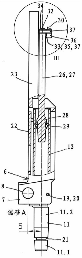
[0037] In the present application, the terms "upper" and "lower" and "sideways" relate to multichannel pipetting heads which are vertically oriented in a piston-cylinder unit and in which the drive rod is arranged above the pin.

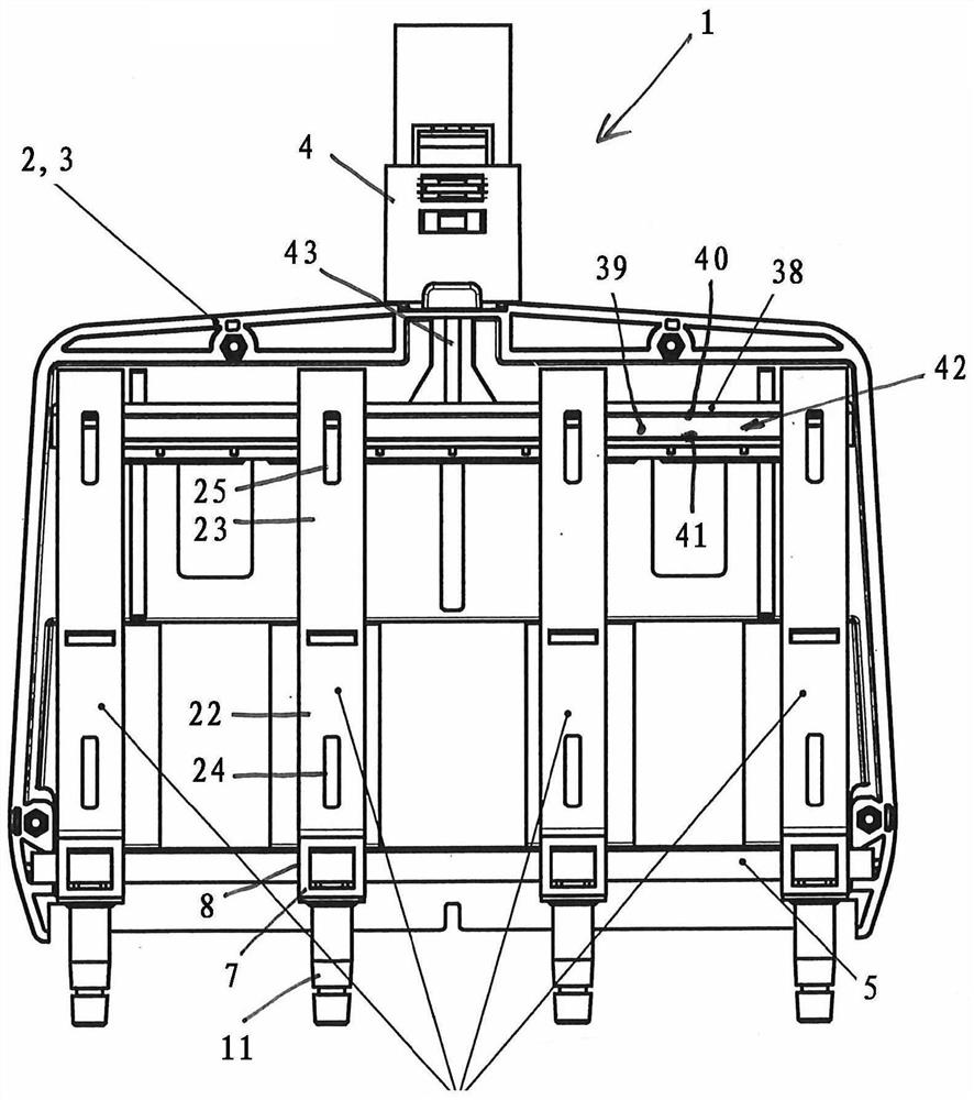
[0038] according to Figures 1 to 3 , the multichannel pipetting head 1 has a support structure 2 which is formed by a two-part housing 3 . exist figure 1 In , the front housing part is removed so that only the rear housing part is shown. Alternatively, the support structure can also be formed by a chassis, which is covered with a housing.

[0039] The casing 3 is basically box-shaped. On the upper edge of the housing 3 , a fastening pin 4 protrudes vertically upwards, said fastening pin being used for connection to the upper part of the pipette.

[0040] A horizontal shaft 5 with a circular cross section is held in the housing. On the shaft 5 a plurality of guides 6 (in the example 4) are displaceable in the horizontal direction and are mounted...


PUM


Abstract

A multichannel pipetting head comprises a horizontal plunger actuator comprising at least one groove with an upper boarder, a lower boarder, and a lateral opening; a drive rod for shifting the piston manipulator in the vertical direction, piston-cylinder units, with each comprising a hollow cylinder and a piston which engages therein from above and is sealed relative to the cylinder, said piston engaging with a piston head through the opening into the groove; a guide device which can be moved along a horizontal axis, on each guide device holding the cylinder body and a pin which protrudes downward, is hollow and is connected to a through-hole in the lower end of the cylinder body, wherein each piston head has an extended upper contact position on the upper side, which contacts the upper delimiting portion, and an extended lower contact position on the lower side, which is offset laterally from the upper contact position and contacts the lower delimiting portion.

Description

technical field [0001] The invention relates to a multichannel pipette head comprising pins for clamping pipette tips which are adjustable relative to each other. Background technique [0002] Multichannel pipettes are used especially in laboratories for the simultaneous pipetting of several liquid samples. The liquid sample is received from a series of receptacles in a microtiter plate or from another vessel into a pipette tip releasably connected to a multichannel pipette and released from the pipette tip into a vessel . Multichannel pipettes have multiple pins or shafts to which pipette tips can be clamped. For aspirating the liquid sample into and expulsing the liquid sample from the pipette tip, there are one or more displacement devices which displace an air cushion between the liquid sample and the displacement device. The displacement device is usually implemented as a piston-cylinder unit comprising a cylinder and a piston movable therein. The displacement devic...

Claims


Application Information

Patent Timeline
Patent Type & Authority Applications(China)
IPC IPC(8): B01L3/02
CPCB01L3/021B01L3/0217B01L2200/022B01L3/0227B01L3/0234B01L3/0279
Inventor M·威尔斯H·林克
Owner 埃佩多夫欧洲股份公司
Why Eureka
Try Eureka