Optical module adjusting method, electronic equipment, device, system and storage medium

An adjustment method and optical module technology, which is applied in the field of communication, can solve the problems of sensitive fiber distribution, the inability of optical modules to adjust wavelength adaptively, and the inability to calculate wavelength, etc., to achieve the effect of adaptive adjustment of dispersion

Pending Publication Date: 2021-12-21
ZTE CORP
View PDF0 Cites 2 Cited by
  • Summary
  • Abstract
  • Description
  • Claims
  • Application Information

AI Technical Summary

Problems solved by technology

Taking the 100G PAM4 specification as an example, when the transmission distance is 30km, the variation range of the wavelength is almost compressed to the extreme value, and the transmission distance is 40km, and the wavelength can no longer be calculated according to the relevant technology.
It can be seen that in related technologies, the optical module cannot perform self-adaptive adjustment to the wavelength
[0009] Aiming at the technical problem that the optical module is sensitive to the zero dispersion point distribution of the optical fiber in actual transmission in the related technology, no effective technical solution has been proposed

Method used


Image

  • Optical module adjusting method, electronic equipment, device, system and storage medium
  • Optical module adjusting method, electronic equipment, device, system and storage medium
  • Optical module adjusting method, electronic equipment, device, system and storage medium

Examples


Embodiment Construction

[0037] Embodiments of the present invention will be described in detail below with reference to the drawings and in combination with the embodiments.

[0038] It should be noted that the terms "first" and "second" in the description and claims of the present invention and the above drawings are used to distinguish similar objects, but not necessarily used to describe a specific sequence or sequence.

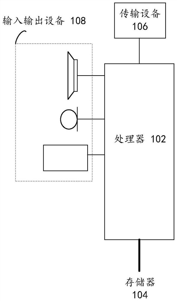
[0039] The method embodiments provided in the embodiments of the present application may be executed in mobile terminals, computer terminals or similar computing devices. Taking running on electronic equipment as an example, figure 2 It is a hardware structural block diagram of an electronic device according to an optical module adjustment method according to an embodiment of the present invention. Such as figure 2 As shown, the electronic device may include one or more ( figure 2 Only one is shown in the figure) a processor 102 (the processor 102 may include but not limite...


PUM


Abstract

The embodiment of the invention provides an optical module adjusting method. The method comprises the following steps: collecting first incident light power of a first optical module, a signal-to-noise ratio of a first signal and an error rate; under the condition that the first incident light power is not within the first power range, adjusting the emission light power of the second optical module; when the first incident light power is within the first power range and the signal-to-noise ratio of the first signal is smaller than or equal to a first threshold value, adjusting the linearity and/or the cross point of an eye pattern corresponding to a sending signal of the second optical module; and adjusting the temperature of the laser in the second optical module according to the first temperature adjustment step length and the bit error rate of the first signal under the condition that the first incident light power is within the first power range and the signal-to-noise ratio of the first signal is greater than a first threshold value. According to the invention, the technical problem that the optical module is sensitive to zero dispersion point distribution of the optical fiber in actual transmission is solved, and the technical effect of adaptive adjustment of dispersion in the optical module is achieved.

Description

technical field [0001] Embodiments of the present invention relate to the communication field, and in particular, relate to an optical module adjustment method, electronic equipment, a device, a system, and a storage medium. Background technique [0002] With the development of the network, the per-wavelength rate level of the current optical fiber communication system has been developed to the single-wavelength baud rate of 53Gbd for a 100G four-level pulse amplitude modulation signal (4Pluse Amplitude Modulation, PAM4 for short). According to the basic principle of optical fiber communication, every time the baud rate doubles, the dispersion tolerance becomes 1 / 4 of the original, and the theoretical reference zero-chirp dispersion tolerance of the 50G baud rate level has been compressed to about ±32ps / nm, thus The dispersion-limited distance calculated according to the dispersion coefficient becomes smaller and smaller. [0003] Table 1. Definitions of optical fiber param...

Claims


Application Information

Patent Timeline
Patent Type & Authority Applications(China)
IPC IPC(8): H04B10/079H04B10/2513H04B10/564G02B6/42
CPCH04B10/07953H04B10/07955H04B10/2513H04B10/564G02B6/4266
Inventor 苏展朱能念
Owner ZTE CORP
Why Eureka
Try Eureka