Full-dustproof single-drive gantry

A gantry drive and single drive technology, applied in the gantry field, can solve the problems of long assembly time, reduced rigidity of the overall mechanism, and difficulty in compressing the size of the platform, so as to avoid deformation and error accumulation, improve rigidity and bearing capacity, and ensure mobile positioning. The effect of precision

Pending Publication Date: 2021-12-10
德康威尔苏州智能科技有限公司
View PDF0 Cites 0 Cited by
  • Summary
  • Abstract
  • Description
  • Claims
  • Application Information

AI Technical Summary

Problems solved by technology

[0004] 1. There are too many mechanical parts on the platform. The guide rails, sliders, the bases of each axis, and the sliding table are connected by screws. The installation steps are cumbersome and the assembly takes a long time
[0005] 2. The linear guide rail of the platform must be installed in the base of the linear motion system through screws and other fasteners, the rigidity of the overall mechanism will be reduced, and it is difficult to apply to high rigidity application requirements
[0006] 3. The guiding accuracy of the linear guide rail of the platform after assembly is affected by the accuracy of the base and the mounting surface, and the accuracy errors are usually superimposed. The accuracy errors of the various components of the two axes are superimposed together, and it is difficult to ensure the mobile positioning accuracy of the uppermost sliding table. , prone to large height fluctuations
[0007] 4. The structure of the linear guide rail used in the platform is fixed, combined into a module, the structure is not compact enough, the space utilization rate is not high, the size of the platform is difficult to compress, the center of gravity of the platform is high, and the operation stability is poor

Method used


Image

  • Full-dustproof single-drive gantry
  • Full-dustproof single-drive gantry
  • Full-dustproof single-drive gantry

Examples


Embodiment Construction

[0038] In order to make the object, technical solution and advantages of the present invention clearer, the present invention will be further described in detail below in conjunction with the accompanying drawings and embodiments. It should be understood that the specific embodiments described here are only used to explain the present invention, not to limit the present invention.

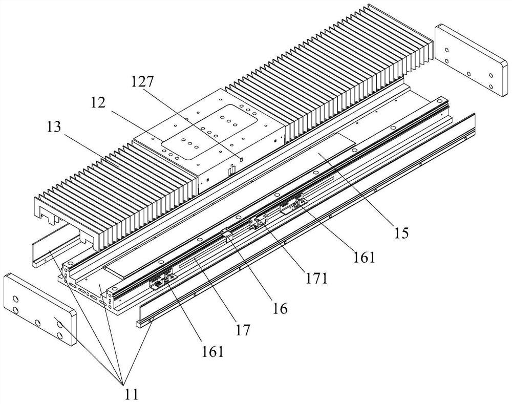
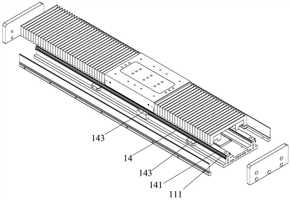
[0039] see figure 1 , a fully dust-proof single-drive gantry, the single-drive gantry includes a beam axis module 1 for carrying objects to drive the objects to move, and a lower axis mold for carrying the beam axis module 1 to drive the movement of the beam axis module 1 Group 2, used to assist the auxiliary shaft 3 of the beam shaft module 1; the beam shaft module 1 is arranged on the lower shaft module 2 and the auxiliary shaft 3, and it is characterized in that the beam shaft module 1 and the lower shaft The modules 2 all include a base, a sliding platform and a telescoping dust cover. Specifica...


PUM


Abstract

The invention belongs to the technical field of gantries, and particularly relates to a full-dustproof single-drive gantry. The single-drive gantry comprises a cross beam shaft module used for bearing an object to drive the object to move, a lower shaft module used for bearing the cross beam shaft module to drive the cross beam shaft module to move, and an auxiliary shaft used for assisting in bearing the cross beam shaft module. The cross beam shaft module is arranged on the lower shaft module and the auxiliary shaft, the cross beam shaft module and / or the lower shaft module comprise / comprises a base, a sliding platform and a telescopic dust cover, two guide rails are arranged on the base, the guide rails and the base are integrally formed, first sliding grooves are formed in the side edges of the two guide rails, a linear motor used for driving the sliding platform to move is further fixedly arranged on the base, the sliding platform is movably arranged on the two guide rails through the first sliding grooves, and the sliding platform is connected with the linear motor. The guide rails and the base are integrally formed, so that the moving positioning precision of an uppermost sliding table is guaranteed, and the rigidity and the bearing capacity of the platform lower shaft module are improved.

Description

technical field [0001] The invention belongs to the technical field of gantry, and in particular relates to the structure of a single-drive gantry. Background technique [0002] The existing linear motor single-drive gantry platforms all use standard rolling linear guide rails as the guiding mechanism. The linear guide rails are connected to the module base through screws, and the guide rail sliders are connected to the sliding plate to realize the linear motion positioning of each axis. However, with the continuous upgrading of equipment, the equipment has higher and higher requirements for the speed and precision of the single-drive gantry, and the requirements for the size of the platform are also getting smaller and smaller. [0003] To meet the requirements of high speed, high acceleration, and small size, the existing standard linear guide rail-guided linear motor single-drive gantry platform has the following problems that need to be improved: [0004] 1. There are t...

Claims


Application Information

Patent Timeline
Patent Type & Authority Applications(China)
IPC IPC(8): H02K41/02H02K5/10H02K11/22
CPCH02K41/02H02K5/10H02K11/22
Inventor 戴健飞柯玉理李庆光戴帝水江雄
Owner 德康威尔苏州智能科技有限公司
Why Eureka
Try Eureka