Walking board conveying table for spraying water pipe pressure groove type template

A conveying table, pressing groove technology, applied in the coating, spray booth, spray device and other directions, can solve the problem of wasting labor and construction period, unsuccessful spray painting, spray paint falling off, etc., to achieve strong linkage, compact structure, good effect Effect

Active Publication Date: 2021-12-07
广东鹏港建筑科技股份有限公司
View PDF6 Cites 0 Cited by
  • Summary
  • Abstract
  • Description
  • Claims
  • Application Information

AI Technical Summary

Problems solved by technology

[0002] In the process of engineering construction, when it is necessary to install line pipes, water pipes or gas pipes on the building, it is usually slotted directly on the concrete. This method wastes materials, labor and construction period, but now it is better The method is to use the water pipe groove plate to form the water pipe groove, which not only saves materials but also saves the construction period, which is very convenient. However, the water pipe pressure groove plate needs to be painted on the plate during the production process. In order to ensure its smooth use in work, but in the actual use of the water pipe groove pattern plate spraying conveyor table in the prior art, there is no auxiliary blow-drying device on the upper end, resulting in the spray paint sprayed on the pattern plate It is not easy to solidify, so it is easy to cause the paint to stick to the conveyor table during transportation, causing the paint on the template to fall off, making the painting unsuccessful, and the paint on the conveyor table cannot be solidified to a certain extent in the later manual handling process It can also easily cause the paint to peel off

Method used


Image

  • Walking board conveying table for spraying water pipe pressure groove type template
  • Walking board conveying table for spraying water pipe pressure groove type template
  • Walking board conveying table for spraying water pipe pressure groove type template

Examples


Embodiment Construction

[0022] The following will clearly and completely describe the technical solutions in the embodiments of the present invention with reference to the accompanying drawings in the embodiments of the present invention. Obviously, the described embodiments are only some, not all, embodiments of the present invention. Based on the embodiments of the present invention, all other embodiments obtained by persons of ordinary skill in the art without making creative efforts belong to the protection scope of the present invention.

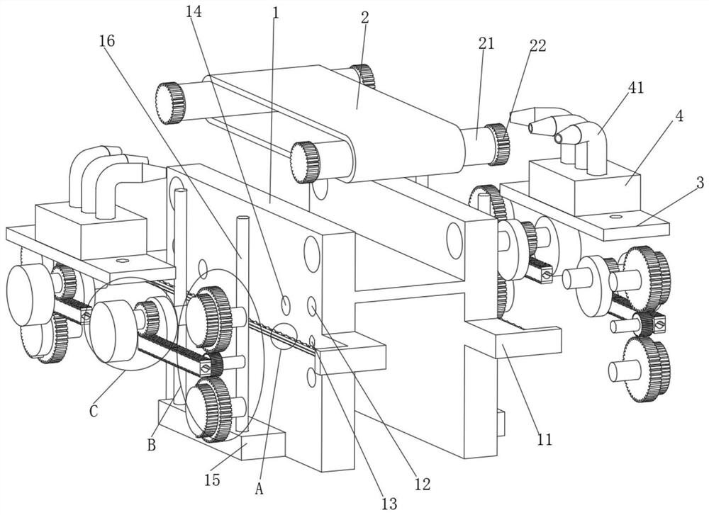
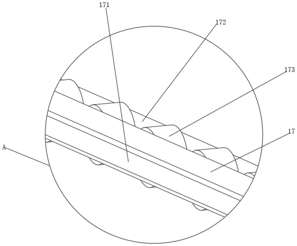
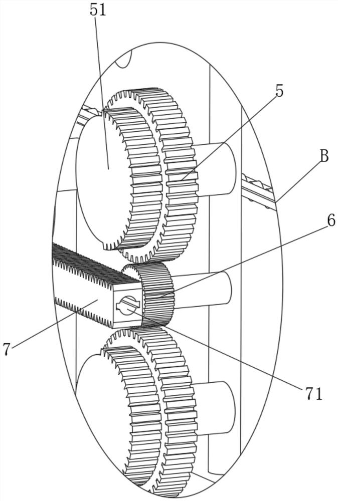
[0023] see Figure 1 to Figure 4 , the present invention provides a technical solution:

[0024] A conveying platform for spraying water pipe pressure groove type plates, including a conveying platform 1, L-shaped frames 11 are welded and fixed symmetrically on both ends and both sides of the conveying platform 1, and the L-shaped frames 11 at both ends are welded and fixed The rack support device and the rack support device include a support rod 17 and a run...


PUM


Abstract

The invention relates to the technical field of aluminum template production, in particular to a walking board conveying table for spraying a water pipe pressure groove type template. The table comprises a conveying table, L-shaped frames are symmetrically welded and fixed at two ends and two sides of the conveying table respectively, a rack supporting device is welded and fixed between the L-shaped frames at the two ends, first shaft holes are symmetrically formed in the two ends and the two sides of the conveying table correspondingly, the number of the first shaft holes in each side is four, the number of the first shaft holes in the upper sides of the L-shaped frames is two, the number of the first shaft holes in the lower sides of the L-shaped frames is two, the first shaft holes in the two sides of the L-shaped frames are symmetrical about the L-shaped frames, rack driving devices are inserted into the middles of the first shaft holes, air blowers are arranged on the two sides of the conveying table, under the action of an air blowers, a certain blow-drying effect can be achieved on a template on the conveying table, so that spray paint on the template conveyed on the conveying table can be solidified to a certain degree, it is guaranteed that the spray paint cannot prone to falling off in the template conveying process, and later work is facilitated.

Description

technical field [0001] The invention relates to the technical field of aluminum formwork production, in particular to a plate-moving conveying platform for spraying water pipe grooved plates. Background technique [0002] In the process of engineering construction, when it is necessary to install line pipes, water pipes or gas pipes on the building, it is usually slotted directly on the concrete. This method wastes materials, labor and construction period, but now it is better The method is to use the water pipe groove plate to form the water pipe groove, which not only saves materials but also saves the construction period, which is very convenient. However, the water pipe pressure groove plate needs to be painted on the plate during the production process. In order to ensure its smooth use in work, but in the actual use of the water pipe groove pattern plate spraying conveyor table in the prior art, there is no auxiliary blow-drying device on the upper end, resulting in th...

Claims


Application Information

Patent Timeline
Patent Type & Authority Applications(China)
IPC IPC(8): B05B13/02B05B16/20B05D3/04
CPCB05B13/0221B05B16/20B05D3/0406Y02P70/10
Inventor 肖庆辉杨建中郭权周麦琼
Owner 广东鹏港建筑科技股份有限公司
Why Eureka
Try Eureka