
Core strapping machine with tension controller

A technology of tension controller and strapping machine, which is applied to the parts of strapping machinery and strapping materials, etc., which can solve the problems that the core cannot be bundled and affects the product process, etc., and achieve the effect of expanding the tension and ensuring the tension

Active Publication Date: 2021-11-30
广州坤江汽车配件工业制造有限公司
View PDF8 Cites 0 Cited by
  • Summary
  • Abstract
  • Description
  • Claims
  • Application Information

AI Technical Summary

Problems solved by technology

[0002] In the production process of the core body, it is necessary to use iron wires to bind the core body. After binding, the core body needs to be stable, so the iron wire needs to have a certain tension, so that the core body after binding can be used. When the core body is bundled, if the tension of the iron wire changes, the core body cannot be bundled well, which will affect the subsequent process of the product. Therefore, we propose a core body strapping machine with a tension controller

Method used


Image

  • Core strapping machine with tension controller
  • Core strapping machine with tension controller
  • Core strapping machine with tension controller

Examples


Embodiment 1

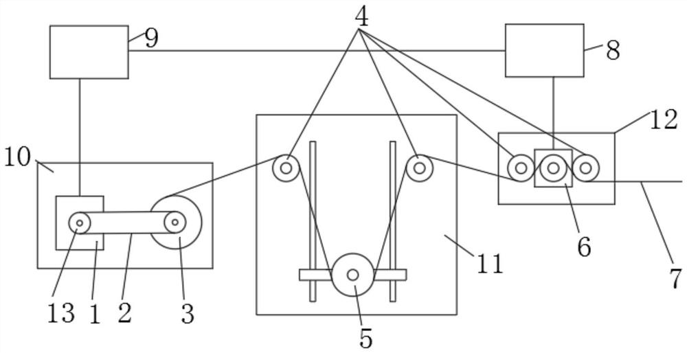
[0024] refer to figure 1 A kind of core binding machine with a tension controller shown includes a fixed bracket 10, a mounting bracket 11 and a connecting bracket 12 arranged in sequence, and the fixing bracket 10, the mounting bracket 11 and the connecting bracket 12 can be any of the prior art One, the side of the fixed bracket 10 is equipped with a material cutting mechanism 3 and a servo motor 1, the material cutting mechanism 3 and the servo motor 1 can be any one in the prior art, the side of the material cutting mechanism 3 and the servo motor 1 All are equipped with synchronous wheel 13, two synchronous wheels 13 are connected by synchronous belt 2, synchronous wheel 13, synchronous belt 2 can be any one in the prior art, and the side portion of mounting bracket 11 is equipped with buffer wheel 5, and connecting bracket The side portion of 12 is equipped with tension sensor 6, and both sides of tension sensor 6 and buffer wheel 5 are all provided with guide wheel 4, a...

Embodiment 2

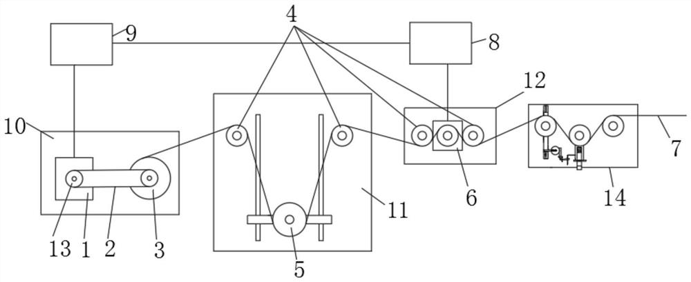
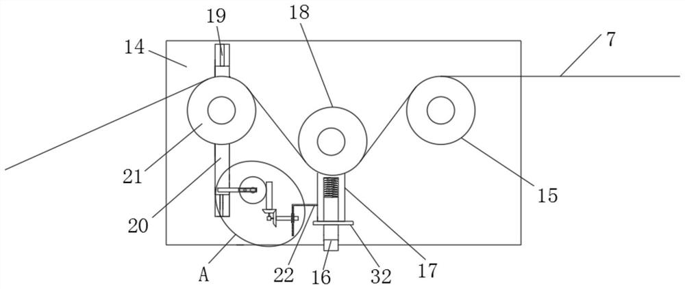
[0028] On the basis of embodiment 1, with reference to Figure 2-4As shown, one side of the connecting bracket 12 is provided with an adjusting bracket 14, and the adjusting bracket 14 can be any one in the prior art. It can be installed on the L-shaped rectangular column 16 on the side of the adjustment bracket 14 by means of welding in the prior art. The L-shaped rectangular column 16 is slidably sleeved with a rectangular block 17. The top of the L-shaped rectangular column 16 can be passed through the existing technology. The mode of welding is equipped with spring, fixed wheel 15, L-shaped rectangular column 16, rectangular block 17, spring can be any one in the prior art, and spring is in stretched state, and the deformation amount that its stretching produces is with binding iron wire 7 The tension is the same, the top of the spring is connected with the rectangular block 17, the side of the rectangular block 17 is rotated with a tension moving wheel 18, the tension mov...


PUM


Abstract

The invention discloses a core strapping machine with a tension controller. The core strapping machine comprises a fixing support, a mounting support and a connecting support which are sequentially arranged, a cutting mechanism and a servo motor are mounted on the side portion of the fixing support, synchronous wheels are mounted on the side portion of the cutting mechanism and the side portion of the servo motor, the two synchronous wheels are connected through a synchronous belt. A buffer wheel is installed on the side portion of the mounting support, a tension sensor is installed on the side portion of the connecting support, and guide wheels are arranged on the two sides of the tension sensor and the two sides of the buffer wheel. When the core strapping machine is used, if the tension of an iron wire changes, the tension sensor can sense the change, then a signal is transmitted to the servo motor, the servo motor transmits the speed and power to the cutting mechanism through the synchronous belt, and therefore the tension of follow-up iron wire conveying can be adjusted, the steel wire reaches the tension needed by product strapping, and the tension of the steel wire after core strapping is effectively ensured to meet the requirements of subsequent procedures of products.

Description

technical field [0001] The application relates to the technical field of strapping machines, in particular to a core strapping machine with a tension controller. Background technique [0002] In the production process of the core body, it is necessary to use iron wires to bind the core body. After binding, the core body needs to be stable, so the iron wire needs to have a certain tension, so that the core body after binding can be used. When the core body is bundled, if the tension of the iron wire changes, the core body cannot be bundled well, which will affect the subsequent process of the product. For this reason, we propose a core body strapping machine with a tension controller. Contents of the invention [0003] The purpose of this application is to provide a core binding machine with a tension controller. If the tension of the iron wire changes when the application is in use, the tension sensor will sense the change and then transmit the signal to the servo motor. ...

Claims


Application Information

Patent Timeline
Patent Type & Authority Applications(China)
IPC IPC(8): B65B13/22B65B13/18B65B13/02
CPCB65B13/22B65B13/18B65B13/02
Inventor 刘鸿坤丰尧叶志鹏邓志文
Owner 广州坤江汽车配件工业制造有限公司
Learn More