
Method for disassembling and assembling spinning assembly

A technology of spinning assembly and disassembly method is applied in the disassembly and assembly field of spinning assembly, which can solve the problems of high requirements on workers' height and overall physical fitness, low safety factor, high labor intensity, etc., so as to reduce the labor intensity and The effect of high labor cost and high safety

Active Publication Date: 2021-11-26
WUJIANG LANGKE CHEM FIBER
View PDF15 Cites 0 Cited by
  • Summary
  • Abstract
  • Description
  • Claims
  • Application Information

AI Technical Summary

Problems solved by technology

[0005] 1. Each time a spinning unit needs to be replaced, the cooperation of many people is required, the labor cost is high, and the efficiency is low;
[0006] 2. Since the weight of a single spinning component is about 15KG, and the height of the component hole on the spinning box is up to two meters, the whole loading and unloading process is labor-intensive and requires high height and overall physical fitness of workers;
[0007] 3. There is a danger of falling off the spinning components during loading and unloading, and the safety factor is low, threatening the lives of workers;
[0008] 4. When the spinning assembly is installed on the thread, it is difficult to perform alignment for a while, and it is difficult to assemble the spinning assembly to the spinning equipment without some guiding operations

Method used


Image

  • Method for disassembling and assembling spinning assembly
  • Method for disassembling and assembling spinning assembly
  • Method for disassembling and assembling spinning assembly

Examples


Embodiment Construction

[0039] In order to make the above-mentioned purpose, features and advantages of the present application more obvious and understandable, the specific implementation manners of the present application will be described in detail below in conjunction with the accompanying drawings. In the following description, numerous specific details are set forth in order to provide a thorough understanding of the application. However, the present application can be implemented in many other ways different from those described here, and those skilled in the art can make similar improvements without departing from the connotation of the present application, so the present application is not limited by the specific embodiments disclosed below.

[0040] In the description of the present application, it should be understood that the terms "center", "longitudinal", "transverse", "length", "width", "thickness", "upper", "lower", "front", " Back", "Left", "Right", "Vertical", "Horizontal", "Top", "...


PUM


Abstract

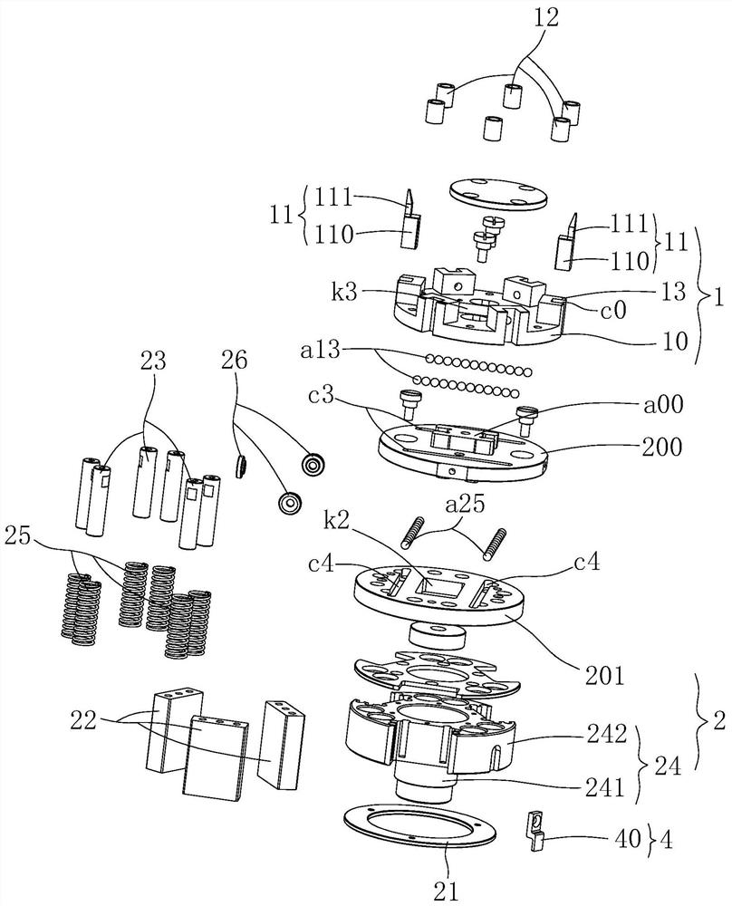
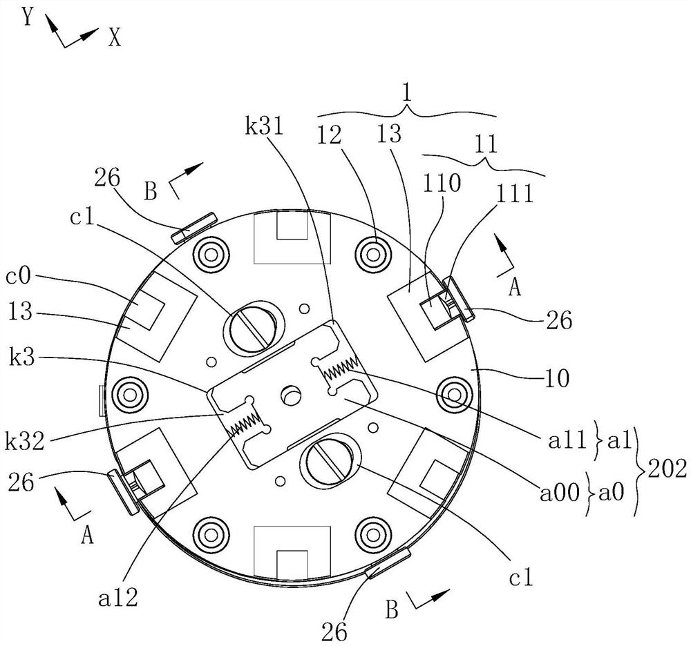
The invention relates to a method for disassembling and assembling a spinning assembly. The method comprises the following steps: S1, aligning a disassembling and assembling head with a disassembling and assembling connector, and rotating around a Z axis to adjust and align in the process of adjusting the movement of the disassembling and assembling head relative to the spinning assembly in the X-axis, Y-axis and Z-axis directions; and S2, enabling the disassembling and assembling head to rotate around the Z axis for disassembly and assembly, and during disassembly and assembly, adopting a power device to drive the disassembling and assembling head and the spinning assembly to synchronously rotate reversely around the Z axis and gradually descend until the spinning assembly is separated from the spinning equipment; during installation, adopting the power device to drive the disassembling and assembling head and the spinning assembly to move synchronously, enabling the upper end of the spinning assembly to be aligned with spinning equipment, and enabling the disassembling and assembling head and the spinning assembly to synchronously rotate reversely for N circles and then rotate forwards synchronously to complete assembly of the spinning assembly. On one hand, through the movement of the X-axis, the Y-axis, the Z-axis and the Z-axis steering, a plug-in module and the disassembly and assembly connector can be quickly and accurately connected in an aligned and plug-in mode; and on the other hand, during assembling, the spinning assembly can be guided in time, and therefore the spinning assembly can be assembled more efficiently and accurately.

Description

technical field [0001] The invention belongs to the technical field of assembly and disassembly of spinning components, and in particular relates to a method for disassembling and assembling spinning components. Background technique [0002] In the production process of spinning, when the melt pressure in the spinning box approaches or exceeds the set value, if it continues to run, it will affect the safety of the spinning box and cause melt leakage accidents, and such accidents mainly It is because the filter screen in the spinning assembly is polluted in a large area, or a large number of spinneret holes are blocked. Therefore, the spinning assembly needs to be replaced in time in production. [0003] At present, the spinning assembly is mainly replaced manually, that is, when installing the spinning assembly, one person uses a special fork to place the spinning assembly on the tightening wrench, and the other lifts the wrench with the spinning assembly up to The correspo...

Claims


Application Information

Patent Timeline
Patent Type & Authority Applications(China)
IPC IPC(8): B23P19/06B23P19/04
CPCB23P19/06B23P19/04
Inventor 卢思源卢贤生葛炜许华强
Owner WUJIANG LANGKE CHEM FIBER
Learn More