Non-isolated three-phase rectification converter and control method thereof

A three-phase rectification, non-isolated technology, which is applied in the directions of converting DC power input to DC power output, AC power input to DC power output, and irreversible AC power input to DC power output, etc., which can solve inappropriate, Problems such as large loss and many devices in the conduction path achieve the effects of reduced limitation, reduced control difficulty, and low loop conduction resistance

Pending Publication Date: 2021-10-15
深圳市高益智能电气有限公司
View PDF0 Cites 0 Cited by
  • Summary
  • Abstract
  • Description
  • Claims
  • Application Information

AI Technical Summary

Problems solved by technology

[0004] The purpose of the present invention is to propose a non-isolated three-phase rectifier converter and its control method to solve the problems in the above-mentioned prior art that there are too many diversion path devices and the large loss caused by the incomplete utilization of the diversion capacity of the step-down switching device. Technical issues suitable for applications in places with limited volume or relatively high cost requirements

Method used


Image

  • Non-isolated three-phase rectification converter and control method thereof
  • Non-isolated three-phase rectification converter and control method thereof
  • Non-isolated three-phase rectification converter and control method thereof

Examples


Embodiment 1

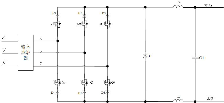
[0040] Such as Figure 4 As shown, this embodiment proposes a non-isolated three-phase rectifier converter, an input rectifier bridge group, a step-down switch unit and an energy storage freewheeling unit; the input end of the input rectifier bridge group is connected to an external three-phase three-wire The power supply (or the output end of a three-phase three-wire power supply with a filter) is connected, the output end of the input rectifier bridge group is connected to the input end of the step-down switch unit, and the output end of the step-down switch unit is connected to the input end of the step-down switch unit. Energy storage freewheeling unit connection. The external three-phase three-wire power supply includes A phase, B phase and C phase. The input rectifier bridge group includes first to third rectifier bridges FB1 to FB3, the first to third rectifier bridges are diode full-bridge rectifier bridges, and the interior is composed of four diodes (for the conveni...

Embodiment 2

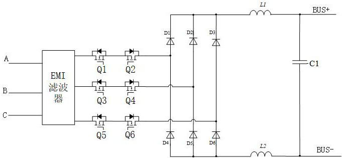
[0069] Such as Figure 14 As shown, this embodiment proposes a modified and modified implementation of the non-isolated three-phase rectifier converter in Embodiment 1. In this embodiment, a non-isolated three-phase rectifier converter is proposed, including at least two three-phase rectifier converters as described in Embodiment 1 connected in parallel, and the switching tubes between each three-phase rectifier converter are driven to Interleaved mode works. In order to make the AC input current easier to achieve continuous.

[0070] Through the aforementioned "high" and "middle" drive signal control methods, at least two (denoted as N) parallel-connected three-phase rectifier converters can be controlled respectively, and the switching tube cycle of N parallel-connected three-phase rectifier converters The internal working phase differs by 1 / N high-frequency switching cycles; therefore, the current at the AC input terminal can form a multi-phase interleaved parallel connec...


PUM


Abstract

The invention relates to the field of power electronics, in particular to a non-isolated three-phase rectifier converter and a control method thereof, and the three-phase rectifier converter comprises an input rectifier bridge group, a step-down switch unit and an energy storage follow current unit; and the input end of the input rectifier bridge group is connected with an external three-phase three-wire power supply, the input end of the step-down switch unit is connected with the output end of the rectifier bridge group, and the output end of the step-down switch unit is connected with the energy storage follow current unit. The converter is simple in structure and simple in control method, the rectifier bridge and the step-down switch tube in the converter can be reused to the maximum extent, and the converter has very obvious advantages in occasions with medium and high power and requiring high efficiency and high power density.

Description

technical field [0001] The invention relates to the field of power electronics, in particular to a non-isolated three-phase rectifier converter and a control method thereof. Background technique [0002] As the current power of electrical equipment is increasing, more and more electrical equipment adopts the three-phase power supply mode. If the electrical equipment does not have the power factor correction (PFC) function, it will greatly damage the power quality of the power grid, seriously Sometimes even lead to the paralysis of the grid. In order to meet the quality requirements of the power grid, reduce harmonic pollution to the power grid or cause unnecessary transmission burden on the distribution network, the three-phase electrical equipment must have the PFC function or add a filter device to meet the requirements of relevant regulations. [0003] Generally speaking, for a three-phase AC input rectifier conversion circuit, if the PFC (power factor correction) functi...

Claims


Application Information

Patent Timeline
Patent Type & Authority Applications(China)
IPC IPC(8): H02M7/08H02M7/217H02M3/158
CPCH02M7/08H02M7/2173H02M3/1584
Inventor 李伦全李玲陈乾宏
Owner 深圳市高益智能电气有限公司
Why Eureka
Try Eureka