Three-phase rectification converter and control method

A technology of three-phase rectification and converter, which is applied in the direction of converting AC power input into DC power output, output power conversion device, electrical components, etc. Many, not suitable for cost requirements and other issues, to achieve the effects of reduced limitation, low loop conduction impedance, and reduced control difficulty

Pending Publication Date: 2021-10-26
NANJING UNIV OF AERONAUTICS & ASTRONAUTICS +1
View PDF0 Cites 0 Cited by
  • Summary
  • Abstract
  • Description
  • Claims
  • Application Information

AI Technical Summary

Problems solved by technology

[0004] The purpose of the present invention is to provide a three-phase rectifier converter and a control method to solve the problems caused by the need for multiple transformations of the two-stage converter in the above-mentioned prior art, the large number of diversion path devices and the inability to fully utilize the diversion capacity of the step-down switching device. The loss is large, so it is not suitable for the technical problem of application in places with relatively high cost requirements

Method used


Image

  • Three-phase rectification converter and control method
  • Three-phase rectification converter and control method
  • Three-phase rectification converter and control method

Examples


Embodiment 1

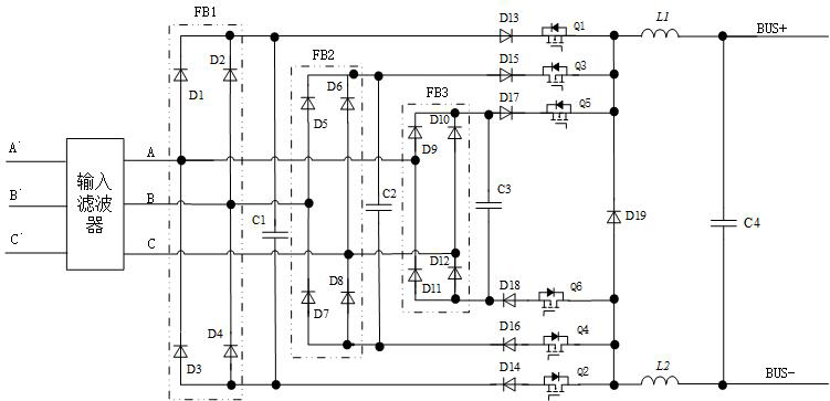
[0048] Such as image 3 As shown, a non-isolated three-phase rectifier converter includes an input rectifier bridge group, a step-down switch unit and an energy storage freewheeling unit; the input rectifier bridge group includes first to third rectifier bridges FB1~FB3, so The first to third rectifier bridges FB1 to FB3 all include four diodes, and the four diodes are connected in series in pairs in the same direction to form two bridge arm groups with the same function, and the two bridge arm groups are connected in parallel to form two AC The input port is the midpoint of two diodes connected in series in the bridge arm group, a positive rectification output terminal is the cathode of the bridge arm group, and a rectification output negative terminal is the anode of the bridge arm group; the step-down switch unit includes the first The thirteenth to the eighteenth diodes D13~D18 and the first to the sixth switching tubes Q1~Q6, the energy storage freewheeling unit includes ...

Embodiment 2

[0082] Such as Figure 13 As shown, embodiment 2 proposes a modified embodiment based on embodiment 1, including at least two non-isolated three-phase rectifier converters as described in embodiment 1, each non-isolated three-phase The rectifier converters are connected in parallel, and the working phases of the first to sixth switching tubes of each non-isolated three-phase rectifier converter are interleaved according to 1 / N high-frequency switching cycles, where N is a parallel non-isolated three-phase Total number of rectifier converters.

[0083] The control method of embodiment 2 is the same as that of embodiment 1. Through the "high" and "middle" mode PWM drive signal control method described in embodiment 1, N non-isolated three-phase rectifier converters connected in parallel can be respectively Control, the working phases of the first to sixth switching tubes of N parallel-connected non-isolated three-phase rectifier converters are interleaved according to 1 / N high-...


PUM


Abstract

The invention relates to a three-phase rectification converter and a control method. The three-phase rectification converter comprises an input rectifier bridge group, a step-down switch unit and an energy storage follow current unit, the input end of the input rectifier bridge group is connected with an external three-phase three-wire power supply, the input end of the step-down switch unit is connected with the output end of the rectifier bridge group, and the output end of the step-down switch unit is connected with the energy storage follow current unit. Middle-mode PWM driving signals and high-mode PWM driving signals are applied to the switching tubes, the input rectifier bridge and the step-down switch in the three-phase rectification converter are multiplexed to the maximum extent, and the converter has quite obvious advantages in occasions where medium and large power is needed and high efficiency and high power density are needed.

Description

technical field [0001] The present application relates to the technical field of power electronics, in particular to a three-phase rectifying converter and a control method. Background technique [0002] At present, the power of electrical equipment is getting larger and larger, and more and more electrical equipment adopts three-phase power supply mode. If the electrical equipment does not have the power factor correction (PFC) function, it will greatly damage the power quality of the grid. In severe cases It may even lead to the breakdown of the power grid. In order to meet the quality requirements of the power grid, reduce harmonic pollution to the power grid or cause unnecessary transmission burden on the distribution network, three-phase electrical equipment must have PFC function or add filtering devices to meet the requirements of relevant regulations. [0003] Generally speaking, for the rectification conversion circuit with three-phase AC input, if PFC function is ...

Claims


Application Information

Patent Timeline
IPC IPC(8): H02M7/219H02M7/217H02M1/44
CPCH02M7/219H02M7/2173H02M1/44Y02B70/10
Inventor 李伦全陈乾宏刘斌
Owner NANJING UNIV OF AERONAUTICS & ASTRONAUTICS
Why Eureka
Try Eureka