An aircraft guidance system and method for realizing landing angle constraints

A technology of aircraft and drop angle, applied in the field of aircraft guidance, can solve problems such as the inability to achieve the attack target and the constraints of the drop angle of the aircraft, and achieve the effect of improving damage capability and flexible use

Active Publication Date: 2022-07-19
BEIJING INSTITUTE OF TECHNOLOGYGY +2
View PDF5 Cites 0 Cited by
  • Summary
  • Abstract
  • Description
  • Claims
  • Application Information

AI Technical Summary

Problems solved by technology

[0002] When the traditional guidance aircraft intercepts the target, its proportional guidance form is relatively simple. When it is necessary to specify the position of the target, especially when it is necessary to attack the weakest position of the target, such as the top, the aircraft is usually required to be able to fly with a larger landing speed. At this time, the traditional proportional guidance form cannot realize the constraint of the falling angle of the aircraft, and thus cannot attack the weak position of the target with a larger falling angle

Method used

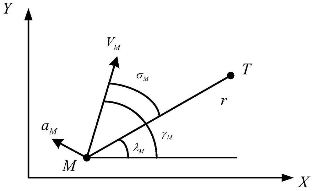

Image

  • An aircraft guidance system and method for realizing landing angle constraints
  • An aircraft guidance system and method for realizing landing angle constraints
  • An aircraft guidance system and method for realizing landing angle constraints

Examples


experiment example 1

[0119] Selecting a flight model capable of realizing falling angle constraints, the aircraft is equipped with an aircraft guidance system with falling angle constraints, and the system includes that the guidance system includes a projectile sight angle measurement module, a guidance law solving module and an execution module. The projectile target The line-of-sight measurement module is used to measure the missile line-of-sight angle of the aircraft in real time.

[0120] After the aircraft starts control, the guidance law calculation module calculates the guidance law in real time according to the measured sight angle of the projectile, and the execution module can control the movement of the aircraft according to the calculated guidance law information.

[0121] Wherein, the guidance law calculation module can obtain the guidance law by calculating the following formula (1)

[0122]

[0123] In the formula, B=-w|s| 1 / 2 sgn(s)+ξ,

[0124] Among them, a m Represents th...

experiment example 2

[0148] Select the flight model that can realize the fall angle constraint. The aircraft is installed with the same aircraft guidance system with the fall angle constraint as the experimental example 1. The system includes the guidance system including the projectile line of sight angle measurement module, guidance law calculation module and execution module. module, the bullet line of sight angle measurement module is used to measure the bullet line of sight angle of the aircraft in real time,

[0149] After the aircraft starts control, the guidance law calculation module calculates the guidance law in real time according to the measured sight angle of the projectile, and the execution module can control the movement of the aircraft according to the calculated guidance law information.

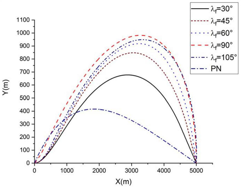
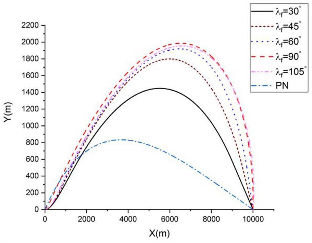
[0150] In this experiment, r=5000m, V m = 300m / s, aircraft start coordinate X M =0m, Y M =0m; fixed target coordinate X T =1000m, Y T = 0m for ballistic simulation, in which the landing an...


PUM


Abstract

The invention discloses an aircraft guidance system and method for realizing the landing angle constraint. The system can firstly set the launching angle of the aircraft by inputting the desired landing angle and target distance coordinates; Then measure the sight angle of the projectile of the aircraft in real time, and transmit the measured sight angle of the projectile to the guidance law calculation module in real time; the guidance law calculation module solves the problem in real time according to the measured sight angle after the aircraft starts control. The guidance law is calculated, and the calculated guidance law information is transmitted to the execution module in real time; the execution module can control the movement of the aircraft according to the calculated guidance law information, thereby completing the present invention to realize the landing angle constraint of the aircraft.

Description

technical field [0001] The invention relates to the technical field of aircraft guidance, in particular to an aircraft guidance system and method for realizing landing angle constraints. Background technique [0002] When the traditional guided aircraft intercepts the target, its proportional guidance form is relatively simple. When the designated position of the target is required, especially when the weakest position of the target needs to be attacked, such as the top and other positions, the aircraft is usually required to be able to land at a larger angle. At this time, the traditional proportional guidance form cannot realize the constraint of the falling angle of the aircraft, and thus cannot achieve the weak position of the target with a larger falling angle. [0003] Therefore, based on the above problems, there is an urgent need to design a guidance system and method that can realize the restraint of the landing angle of the aircraft. SUMMARY OF THE INVENTION [...

Claims


Application Information

Patent Timeline
Patent Type & Authority Patents(China)
IPC IPC(8): F42B15/01F41G3/00F41G7/34
CPCF42B15/01F41G3/00F41G7/343
Inventor 王伟刘佳琪胡宽容王伟斌王录强南宇翔
Owner BEIJING INSTITUTE OF TECHNOLOGYGY
Why Eureka
Try Eureka