


Quick Research
Generate reliable direction feasibility study reports for your R&D in just a few steps.

Technical Q&A
Discover and master advanced knowledge NOW. Basics, ideas, possibilities, all at once.

Find Solutions
As an expert in R&D theories, this can generate solutions to your technical problems instantly.

Evaluate Feasibility
Analyze your overall solution with one click, know your potential R&D risks in advance.

Monitor Landscape
Get weekly tech updates, stay abreast of the latest tech innovations and key insights.
Replacement structure of discharging device and discharging device
A technology of a discharging device and a material box, which is applied in the direction of coinless or similar appliances, coin-operated equipment for distributing discrete items, and coin-operated equipment for distributing discrete items, and can solve the problem that sheet-like items cannot Applicable, complex operation methods, inconvenient operation, etc., to achieve the effect of reliable anti-theft function, convenient disassembly and maintenance, and precise alignment
- Summary
- Abstract
- Description
- Claims
- Application Information
AI Technical Summary
Problems solved by technology
Method used
Image

Examples
Embodiment 1
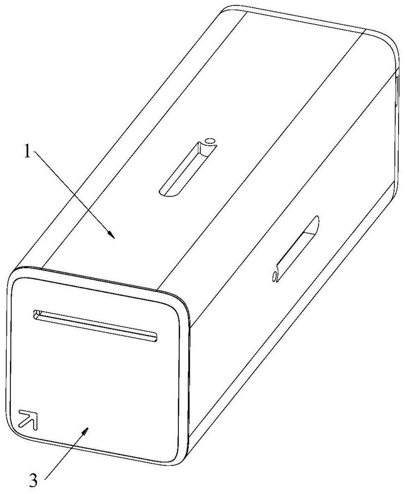
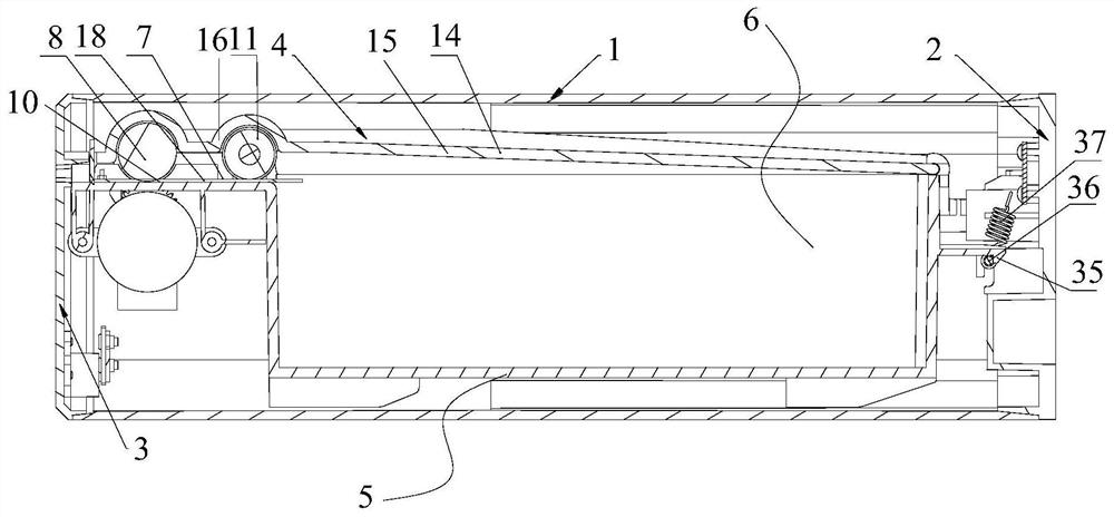
[0042] Such as figure 1 , 2 , 3, 7 and 8, a discharge device includes a hollow shell 1, a rear cover 2 fixed on the rear end of the shell 1 and a magazine assembly 4 slidably installed in the shell 1, the rear cover 2 and the magazine assembly 4 with replacement structure.
[0043] Such as image 3 , 4 , 5 and 6, in the present embodiment, the magazine assembly 4 includes:
[0044] The material box 5 has an accommodating cavity 6 and a discharge port 7 communicating with the accommodating cavity 6. The accommodating cavity 6 is used to install a material belt. The material belt includes a plurality of sheet articles 18 connected in sequence. The material belt is reciprocally bent and folded on the material belt Inside the chamber 6 of the box 5;
[0045] The discharge spindle 8 is rotatably installed at the discharge port 7 of the material box 5, and is used to drive the sheet-shaped article 18 to move out of the material box 5;
[0046] The discharging motor 9 is used t...
Embodiment 2
[0092] The difference between this embodiment and embodiment 1 is that the cutting blade 22 is different, as Figure 9 and 10 As shown, the end of the cutting blade 22 located at the installation end 23 has a special-shaped avoidance opening 33, and the end of the outer packaging connection of two adjacent sheet articles near the installation end 23 has a preset split opening; the special-shaped avoidance opening 33 includes an avoidance side The wall 34 prevents the side wall 34 from facing the separation opening when the cutting blade 22 is in the first position and the sheet-shaped article is moved to the cutting position. Setting the special-shaped avoidance opening 33 and the cutting opening can make the whole structure more compact (the cutting range can be reduced), and is especially suitable for sheet materials with a certain thickness, such as condoms and the like.
[0093]In this embodiment, when the cutting blade 22 is at the first position, the avoiding side wall ...
PUM
 Abstract
Description
Claims
Application Information
 - R&D Engineer
- R&D Manager
- IP Professional
- Industry Leading Data Capabilities
- Powerful AI technology
- Patent DNA Extraction
Browse by: Latest US Patents, China's latest patents, Technical Efficacy Thesaurus, Application Domain, Technology Topic, Popular Technical Reports.
© 2024 PatSnap. All rights reserved.Legal|Privacy policy|Modern Slavery Act Transparency Statement|Sitemap|About US| Contact US: help@patsnap.com