
Conducted interference suppression circuit and power converter

A technology for suppressing circuit and conduction interference. It is used in output power conversion devices, high-efficiency power electronic conversion, and electrical components. It can solve the problem of high cost of winding magnetic loops, and achieve the effect of small size and avoiding differential mode interference.

Pending Publication Date: 2021-09-28
GREE ELECTRIC APPLIANCES INC
View PDF8 Cites 0 Cited by
  • Summary
  • Abstract
  • Description
  • Claims
  • Application Information

AI Technical Summary

Problems solved by technology

[0004] In order to overcome the problem of high cost of winding magnetic rings in the related art, this application provides a conducted interference suppression circuit and power converter

Method used


Image

  • Conducted interference suppression circuit and power converter
  • Conducted interference suppression circuit and power converter
  • Conducted interference suppression circuit and power converter

Examples


Embodiment Construction

[0041] Reference will now be made in detail to the exemplary embodiments, examples of which are illustrated in the accompanying drawings. When the following description refers to the accompanying drawings, the same numerals in different drawings refer to the same or similar elements unless otherwise indicated. The implementations described in the following exemplary embodiments do not represent all implementations consistent with this application. Rather, they are merely examples of apparatuses and methods consistent with aspects of the present application as recited in the appended claims.

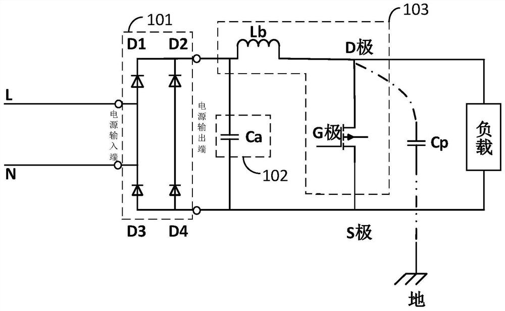
[0042] see figure 2 , figure 2 It is a structural schematic diagram of a conducted interference suppression circuit provided by an embodiment of the present application.

[0043] Such as figure 2 As shown, the conducted interference suppression circuit provided in this embodiment may include: a rectifying unit 101, a first filtering unit 102, and a driving unit 103;

[0044] The r...


PUM


Abstract

The invention relates to a conducted interference suppression circuit and a power converter. The conducted interference suppression circuit comprises a rectification unit, a first filtering unit and a driving unit, the rectification unit comprises a power supply input end and a power supply output end, and the power supply output end is provided with a first output pin and a second output pin; the first output pin is connected with one end of the first filtering unit, and the second output pin is connected with the other end of the first filtering unit; the driving unit is provided with a first input pin, a second input pin, a third output pin and a fourth output pin; the first input pin is connected with the first output pin, and the second input pin is used for accessing a driving signal for driving the unit to work; and the third output pin is connected with the second output pin, and the third output pin and the fourth output pin are used for being connected with a load. Differential mode interference can be avoided only by adding the first filtering unit, excessive magnetic rings are prevented from being added, and more cost is saved.

Description

technical field [0001] The present application relates to the technical field of interference suppression, in particular to a conducted interference suppression circuit and a power converter. Background technique [0002] With the development of power electronics technology, the application of PFC circuits is becoming more and more extensive. The core of switching power supply is the power converter. Conducted interference caused by electromagnetic compatibility (Electro Magnetic Compatibility, EMC) test failed, after connected to the grid, will also cause some pollution to the grid. [0003] In response to this problem, at present, a certain number of turns of magnetic rings (such as ferrite magnetic rings) are wound on the power cord, such as figure 1 As shown, this is equivalent to adding a nonlinear impedance on the line, increasing the impedance of the power supply circuit, increasing the loss of high-frequency interference, and damping the propagation of interference....

Claims


Application Information

Patent Timeline
Patent Type & Authority Applications(China)
IPC IPC(8): H02M1/42H02M1/14H02M1/44H02M1/08
CPCH02M1/42H02M1/14H02M1/44H02M1/08Y02B70/10
Inventor 吴启添吴洪清吴勇濮兴昕杨静怡
Owner GREE ELECTRIC APPLIANCES INC
Learn More