Crane jib lighting system and control method thereof

A lighting system and crane technology, applied to cranes, lighting devices, fixed lighting devices, etc., can solve the problems of follow-up, distracting operators, poor lighting effects, etc., and achieve the effect of simple and convenient operation and convenient and safe operation

Pending Publication Date: 2021-09-03
ANHUI LIUGONG CRANE
View PDF0 Cites 0 Cited by
  • Summary
  • Abstract
  • Description
  • Claims
  • Application Information

AI Technical Summary

Problems solved by technology

There are the following defects in the installation of the boom lighting by thread fixing: 1. The lighting is fixed on the side of the boom, and the angle adjustment of the lighting cannot be realized, and the angle of the lighting cannot be changed with the height of the hoisting object.
2. Existing crane arm lights can only shine in the direction of the arm head, and cannot guarantee sufficient light sources at all angles
3. Most of the light of the existing crane boom lighting is directed to the wall of the boom tube where the lighting is installed, and a small part of the light is directed to the direction of the arm head, but this small part of the light is blocked by the long-angle sensor installed in front of the boom lighting , the lighting effect is not good, and it is not helpful for the operator to judge the hoisting environment
There are the following defects in manually adjusting the angle of the lighting lamp: 1. It is impossible to keep the height of the lighting lamp and the hoisting object in motion
2. If the operator wants to adjust the angle of the lighting lamp during the hoisting process, he needs to adjust the angle of the lighting lamp while operating the lifting operation. This operation distracts the attention of the operator and is not conducive to safe operation.

Method used


Image

  • Crane jib lighting system and control method thereof
  • Crane jib lighting system and control method thereof
  • Crane jib lighting system and control method thereof

Examples


Embodiment Construction

[0030] The present invention will be further described below in conjunction with accompanying drawing:

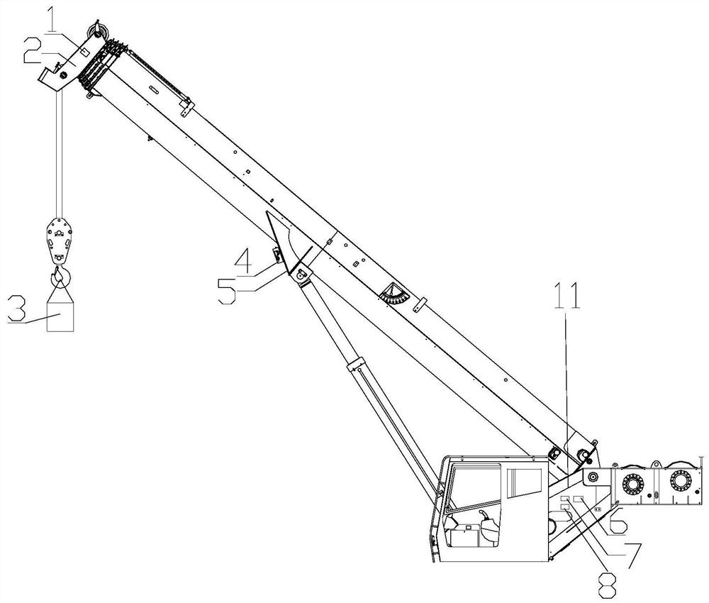
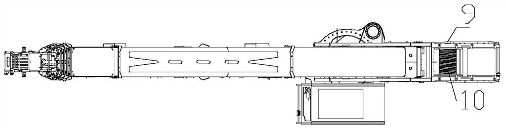
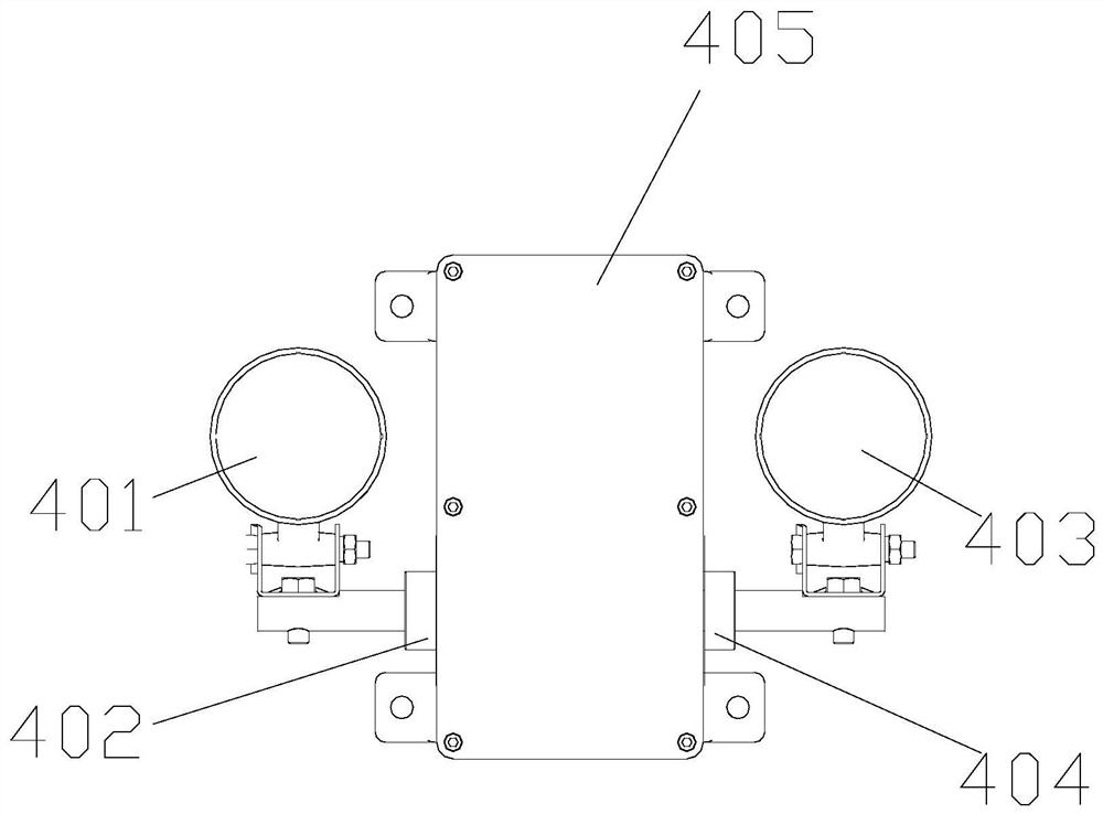
[0031] Such as Figure 1-Figure 4 The shown crane boom lighting system includes a boom, a jib 2 installed on the upper end of the boom, and a luffing rib 5 installed on the lower side of the middle section of the boom. The lighting lamp assembly 4 is installed on the luffing rib 5; the lighting lamp assembly includes a housing 405, a lighting lamp 1 401 and a lighting lamp 2 403; the housing 405 is installed on the luffing rib 5, and the housing The first servo motor 402 and the second servo motor 404 are installed in the body 405; the output shaft of the first servo motor 402 extends to the outside of the casing 405, and the first lamp 401 is installed on the output shaft of the first servo motor 402; The output shaft of the second motor 404 protrudes to the outside of the casing 405, and the second illuminating lamp 403 is installed on the output shaft of the second serv...


PUM


Abstract

The invention relates to a crane jib lighting system and a control method thereof. The system comprises a crane jib, a horse head arm installed at the upper end of the crane jib and a variable-amplitude rib plate installed on the lower side of the middle section of the crane jib, an lighting lamp assembly is installed on the variable-amplitude rib plate, the lighting lamp assembly comprises a shell, a first lighting lamp and a second lighting lamp, the shell is installed on the variable-amplitude rib plate, a first servo motor and a second servo motor are installed in the shell, an output shaft of the first servo motor extends to the outer side of the shell, the first lighting lamp is installed on the output shaft of the first servo motor, an output shaft of the second servo motor extends to the outer side of the shell, the second lighting lamp is installed on the output shaft of the second servo motor, and an angle sensor is installed on the horse head arm. According to the crane jib lighting system and the control method thereof, the defects in the prior art can be overcome, the angle of the lighting system can be adjusted in real time according to the height of a hoisted object, it is ensured that all the angles have the good lighting effect, operation is easy and convenient, and safe operation of operators is facilitated.

Description

technical field [0001] The invention relates to the technical field of cranes, in particular to a crane boom lighting system and a control method thereof. Background technique [0002] There are various dangerous factors when the crane is hoisting at night. When hoisting at night, the crane boom lighting system can follow the pitch angle of the lighting lamp and the height of the hoisting object, and illuminate the hoisting object at any height. The crane jib lighting system can provide operators with a clear and bright operating environment, help operators discover potential dangerous factors in the hoisting process in time, and ensure safe operation of the crane. [0003] The existing crane boom lighting system has the following two installation methods: the first is to fix and install the lighting lamp on the side of the boom, and the second is to adjust the angle of the lighting lamp by manually adjusting the lighting lamp control button. There are the following defects...

Claims


Application Information

Patent Timeline
IPC IPC(8): B66C23/04B66C23/06B66C23/62B66C13/00B66C13/16B66C13/18F21S8/00F21V21/15F21V21/30
CPCB66C23/04B66C23/06B66C23/62B66C13/00B66C13/16B66C13/18F21S8/00F21V21/15F21V21/30
Inventor 柳坤白晓军周赫赫任丹阳高佳佳张金磊金明
Owner ANHUI LIUGONG CRANE
Why Eureka
Try Eureka