
Conveying object distribution device, pneumatic sending system, and sample container sending method

A distribution device and object technology, applied in the direction of conveyor, transportation and packaging, etc., can solve the problem that the structure cannot complete the corresponding transportation, etc., and achieve the effect of fast data acquisition efficiency, high accuracy, and simple structure

Pending Publication Date: 2021-08-24
苏州小甘草智能科技有限公司
View PDF1 Cites 1 Cited by
  • Summary
  • Abstract
  • Description
  • Claims
  • Application Information

AI Technical Summary

Problems solved by technology

[0004] The problem with this structure is that only one length of container can be transported. When there are various lengths of the container and each length of container needs to be transported to a detection department, for example, when there are two types of blood collection tubes, When short blood collection tubes need to be transported to one testing department and long blood collection tubes need to be transported to another testing department, the above structure cannot complete the corresponding transport

Method used


Image

  • Conveying object distribution device, pneumatic sending system, and sample container sending method
  • Conveying object distribution device, pneumatic sending system, and sample container sending method
  • Conveying object distribution device, pneumatic sending system, and sample container sending method

Examples


Embodiment 2

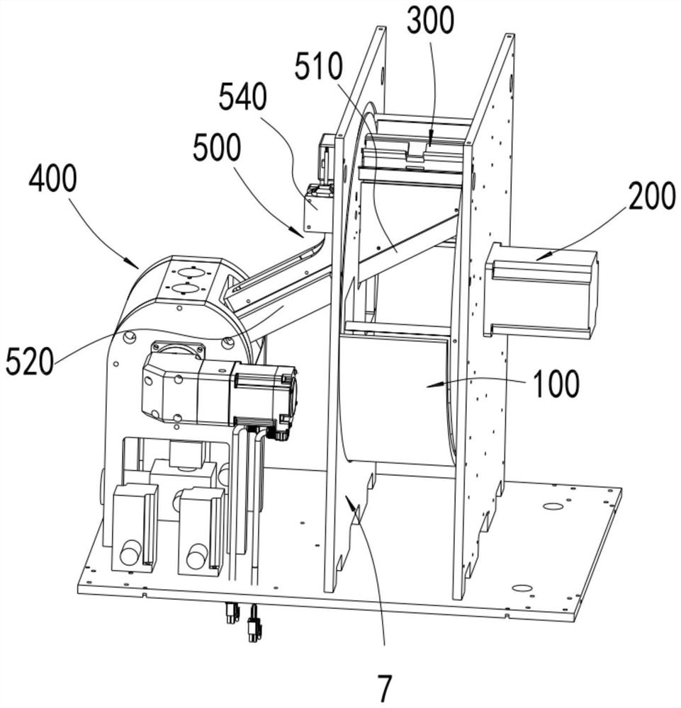
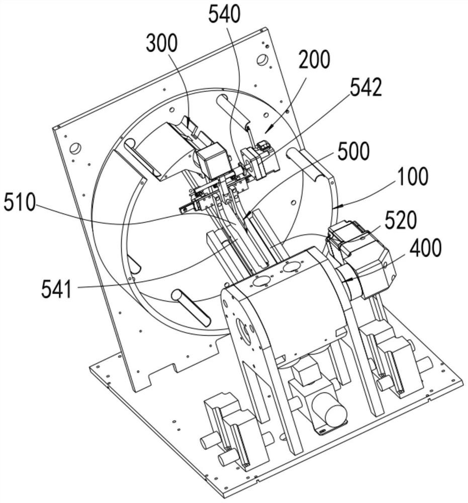
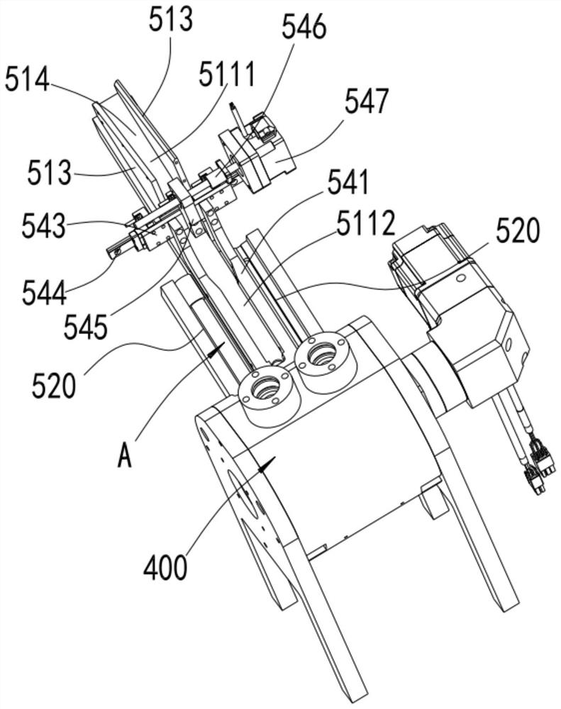
[0088] The difference between this embodiment and embodiment 1 is: as attached image 3 As shown, in this embodiment, the silo 100, the feeding part 200, the buffer storage part 300, etc. in the above-mentioned embodiment 1 are all omitted, and only at least two sending components and the distribution mechanism 500 are provided. At this time, The conveying objects can be directly placed on the unloading chute. At the same time, only one sensor can be set at the unloading chute in the distribution mechanism 500 to determine whether there is a conveying object in the lower section of the unloading chute. During work, no distinction can be made. The length of the object to be conveyed, but by forming two conveying channels to speed up the sending beat of the entire device, so as to improve the sending efficiency.

[0089] Of course, a more optimal structure is a structure that combines the length recognition and direction recognition in the first embodiment above.

Embodiment 3

[0091] This embodiment further discloses a pneumatic sending system, which is used to send various tubular or columnar or bottle-shaped items, preferably for delivery of blood collection tubes, as attached Figure 9 As shown, it includes the delivery object allocation device of the above embodiment or the structure disclosed by the application number 202021337054.4 with only one sending component 400 .

[0092] Here, one sending assembly 400 is taken as an example for illustration. One connection port of the sending assembly 400 is connected to the output pipeline 600, and the other connecting port is connected to the air supply pipeline 700, and the air supply pipeline 700 is used to supply the air to the sending assembly. The sending channel 411 of the sending rotary block 410 of 400 transports gas, so that the delivery object in the sending channel 411 enters the output pipe 600 under the action of air flow and is transported to the corresponding position.

[0093] Among th...

Embodiment 4

[0112] This embodiment further discloses a method for sending blood collection tubes using the above-mentioned pneumatic sending system, which includes the following steps:

[0113] S1, make the blood collection tubes of different lengths enter the feeding chute, determine the length of the blood collection tubes in the feeding chute through the sensor and send it to the control system; when there are only distribution mechanisms and sending components, directly put the blood collection tubes into the On the unloading chute. When there is a silo 100, a feeding part 200 and a buffer storage part 300, the blood collection tube is put into the inlet of the shell, and after the blood collection tube enters the feed bin 100, it is transported by the feeding part 200 and the buffer storage part 300. In the unloading chute.

[0114] S2, the blood collection tube that enters the unloading chute slides to its lower section along the slope and is restricted on the slope by the limit pi...


PUM


Abstract

The invention discloses a conveying object distribution device, a pneumatic sending system and a sample container sending method. According to the conveying object distribution device, a distribution mechanism is arranged to be connected with a plurality of sending assemblies and cache conveying pieces, the distribution mechanism is provided with a discharging sliding way for receiving the conveying objects at the conveying position of the cache conveying piece and at least two material guiding sliding grooves, the lower end of each material guiding sliding groove is in communication with an inlet of one sending assembly, the distribution mechanism is further provided with a structure for recognizing the length of the conveying objects at the discharging sliding way, and according to the recognized length of the conveying objects, the conveying objects at the discharging sliding way are transferred into the material guiding sliding grooves corresponding to the conveying objects with the lengths through a transferring mechanism, so that the conveying objects with the different lengths enter the different sending assemblies to be sent in a classified mode, and the requirement for sending the conveying objects with the different lengths in a classified mode is effectively met.

Description

technical field [0001] The invention relates to the field of automatic conveying equipment, in particular to a conveying object distributing device, a pneumatic sending system and a sending method with sample containers. Background technique [0002] In hospitals, laboratories and other occasions where samples in tubes need to be analyzed and tested, containers such as tubes or bottles containing samples need to be transported from the collection point to the corresponding analysis point for analysis. Conveying of containers such as tubes or bottles. [0003] The application number is 202021337054.4, which discloses a blood collection tube transmission transmitter, which collects the blood collection tubes and transports them to a sending component. By supplying air to the sending component, the blood collection tubes in the sending component are sent to the designated detection through the delivery track. department. [0004] The problem with this structure is that only o...

Claims


Application Information

Patent Timeline
Patent Type & Authority Applications(China)
IPC IPC(8): B65G51/04B65G51/16B65G51/18B65G51/28B65G51/36
CPCB65G51/04B65G51/16B65G51/18B65G51/28B65G51/36B65G2201/0235
Inventor 董振海
Owner 苏州小甘草智能科技有限公司
Learn More