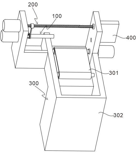
Cpp packaging film winding and storing device
A storage device, packaging film technology, applied in transportation and packaging, strip winding, thin material handling, etc., can solve problems such as increasing the workload of operators
- Summary
- Abstract
- Description
- Claims
- Application Information
AI Technical Summary
Problems solved by technology
Method used
Image
Examples
Embodiment 1
[0031] refer to Figure 1 to Figure 4 , is the first embodiment of the present invention, which provides a cpp packaging film winding and storage device, including a winding unit 100 , a pushing unit 200 , and a storage unit 300 . The winding unit 100 includes a winding roller 101 and a first drive motor 102 connected to the winding roller 101, the winding roller 101 is provided with a hollow cavity, and a tension member 103 is arranged in the hollow cavity, and the winding roller 101 is sleeved on the outside There is a reel 104 . The pushing unit 200 is located above the rewinding unit 100, and includes a second drive motor 201 and a push screw 202 connected to the second drive motor 201. A nut 203 is arranged on the outside of the push screw 202, and the bottom of the nut 203 is connected with a sleeve sleeved on the take-up roller 101. Push block 204 on the outside. The storage unit 300 is located obliquely below the winding unit 100 .
[0032] The winding unit 100 is u...
Embodiment 2
[0036] refer to Figure 1 to Figure 7 , is the second embodiment of the present invention, which is different from the first embodiment in that: the tensioning member 103 includes a control mechanism 103a and a tensioning mechanism 103b connected with the control mechanism 103a, and the control mechanism 103a controls the tensioning member 103 tensioned state, so as to realize the coordinated rotation and separation of the winding roller 101 and the winding drum 104 .
[0037]Further, the side of the winding roller 101 close to the first driving motor 102 is provided with a sliding groove 101a passing through in the transverse direction, and the outer edge of the winding roller 101 is arranged in the tensioning groove 101b. The control mechanism 103a includes a sliding rod 103a-1 arranged in the sliding groove 101a and a pull rod 103a-2 connected with the sliding rod 103a-1. The position block 103a-3 and the limit block 103a-3 are connected with a spring 103a-4. A pulling ri...
Embodiment 3
[0041] refer to Figure 1 to Figure 9 , is the third embodiment of the present invention, which is different from the previous two embodiments in that: a reel storage box 400 is provided on the upper side wall of the storage unit 300, and a reel storage box 400 is provided with a The bottom of the other side of the inclined block 401 is provided with a cylinder outlet 402 , and the upper side wall of the storage unit 300 is provided with a through hole 403 connected with the cylinder outlet 402 . The pushing block 204 is a hollow annular magnetic force block. A magnetic block 104a is disposed on the outer side of the winding drum 104, and a blocking block 104b is disposed at the end away from the magnetic block 104a.
[0042] The outlet port 402 and the winding roller 101 are located on the same axis, and there are multiple groups of stacked winding rollers 104 stored in the winding roller storage box 400, and the bottommost winding roller 104 passes through the through hole ...
PUM
 Abstract
Description
Claims
Application Information
 - R&D
- Intellectual Property
- Life Sciences
- Materials
- Tech Scout
- Unparalleled Data Quality
- Higher Quality Content
- 60% Fewer Hallucinations
Browse by: Latest US Patents, China's latest patents, Technical Efficacy Thesaurus, Application Domain, Technology Topic, Popular Technical Reports.
© 2025 PatSnap. All rights reserved.Legal|Privacy policy|Modern Slavery Act Transparency Statement|Sitemap|About US| Contact US: help@patsnap.com


