
Compressor assembly process

An assembly process and compressor technology, which is applied in the field of compressors, can solve the problems of reducing the assembly accuracy requirements of compressor products, affecting the mass production of compressors, and increasing the operating noise of compressors, so as to ensure smoothness, stability and quality. Excellent effect of reducing compression leakage

Active Publication Date: 2021-10-26
GUANGDONG HESHI AUTOMATION TECH CO LTD
View PDF0 Cites 0 Cited by
  • Summary
  • Abstract
  • Description
  • Claims
  • Application Information

AI Technical Summary

Problems solved by technology

However, in the existing compressor assembly process, there is no step of detecting the eccentricity of the moving plate, and the measurement of the compression leakage can only be carried out after the compressor products are completely assembled.
Once the compression leakage does not meet the requirements, the eccentricity of the moving disk needs to be adjusted. However, at this time, the moving disk is located inside the compressor product, and the static disk assembly needs to be disassembled to adjust the eccentricity of the moving disk, which is time-consuming and laborious.
Moreover, the crankshaft can no longer be taken out from the machine base. If you need to adjust the eccentricity of the moving disc by adjusting the eccentricity of the crankshaft, you can only adjust the eccentricity of the crankshaft manually, and manual alignment is a technical job, which is time-consuming and laborious.
It can be seen that the adjustment of the eccentricity of the moving plate has become a bottleneck problem affecting the mass production of compressors, which in turn reduces the assembly accuracy requirements of compressor products, resulting in instability between the mechanical components of compressor products during operation. As a result, the overall operating noise of the compressor increases, which affects the performance of the product

Method used


Image

  • Compressor assembly process
  • Compressor assembly process
  • Compressor assembly process

Examples


Embodiment Construction

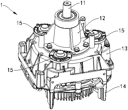
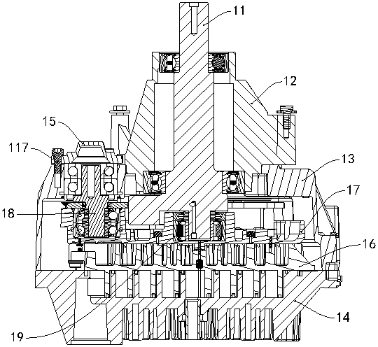
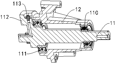
[0045] see figure 1 and figure 2 The compressor assembly 1 includes a crankshaft 11, a machine base 13, three eccentric pins 18, a fixed base 17, a moving disk 16 and a static disk 14, the crankshaft 11 is rotatably supported on the machine base 13, and the moving disk 16 is mounted on a fixed On the seat 17, and the fixed seat 17 is sleeved on the crankshaft 11. Wherein, three eccentric pins 18 are evenly distributed in the circumferential direction of crankshaft 11, and the first end of each eccentric pin 18 is rotatably supported on the base 13, and the second end of each eccentric pin 18 is rotatably supported on a fixed On the base 17, a pressure plate 15 is fastened on the machine base 13 by a screw 117 and covered on the first end of an eccentric pin 18. Moreover, the static disc 14 cooperates with the movable disc 16 and is fixedly installed on the base 13 .

[0046] The assembly process of the compressor in this embodiment includes the assembly steps of the cranks...


PUM


Abstract

The invention provides a compressor assembly process, which includes an eccentricity detection step, and the eccentricity detection step includes: controlling the rotation of the crankshaft of the transmission assembly, and detecting the eccentricity of the moving plate of the transmission assembly; the moving plate of the transmission assembly and the crankshaft of the transmission assembly one end of the connection. In order to reduce compression leakage and ensure the smooth and stable rotation of the rotor, the eccentricity of the rotor should be within a reasonable range. The eccentricity detection step of the compressor assembly process of the present invention is to detect the eccentricity of the moving disk of the transmission assembly when the crankshaft of the transmission assembly is controlled to rotate, that is, to detect the eccentricity of the moving disk before assembling the static disk, so as to avoid If the measurement of the compression leakage after assembly is unqualified, the static disc needs to be disassembled to adjust the eccentricity of the moving disc, which is time-consuming and labor-intensive. The compressor assembling process of the invention has high production efficiency, low production cost, and can meet the requirements of mass production. The compressor product adopting the compressor assembly process of the present invention has high assembly precision and excellent quality.

Description

technical field [0001] The invention relates to the technical field of compressors, in particular to a compressor assembly process. Background technique [0002] The oil-free scroll compressor uses a pair of phase-staggered spirals to move with each other to form a compression chamber that shrinks continuously from the outside to the inside to achieve airflow compression. During the working process of suction, compression and exhaust, the static disk is fixed on the frame, and the movable disk is driven by the crankshaft and controlled by an anti-rotation mechanism, and swings in a plane with a small radius around the center of the base circle of the static disk. The difference from conventional reciprocating rotary compressors is that the relative movement gap between the two spirals of the oil-free scroll compressor is small but does not touch, and the linear velocity of the relative motion of the two spirals is relatively low. According to the above principles, the oil-f...

Claims


Application Information

Patent Timeline
Patent Type & Authority Patents(China)
IPC IPC(8): F04C18/02G01D21/02
CPCF04C18/0215F04C2230/60G01D21/02
Inventor 吴少威李卫彤陈荣
Owner GUANGDONG HESHI AUTOMATION TECH CO LTD
Learn More