Fan impeller

A technology of fan impeller and fan blade, applied in parts of pumping device for elastic fluid, non-variable displacement pump, machine/engine, etc., can solve problems such as damage, and achieve the effect of high fan power and low weight

Active Publication Date: 2021-08-06
MAHLE INT GMBH
View PDF6 Cites 0 Cited by
  • Summary
  • Abstract
  • Description
  • Claims
  • Application Information

AI Technical Summary

Problems solved by technology

[0003] In principle, such a fan wheel or its fan blades must be able to withstand driving through water without being damaged, in particular it must not be allowed to come into contact with other components (such as radiators) to deform and thus be damaged

Method used


Image

  • Fan impeller
  • Fan impeller
  • Fan impeller

Examples


Embodiment Construction

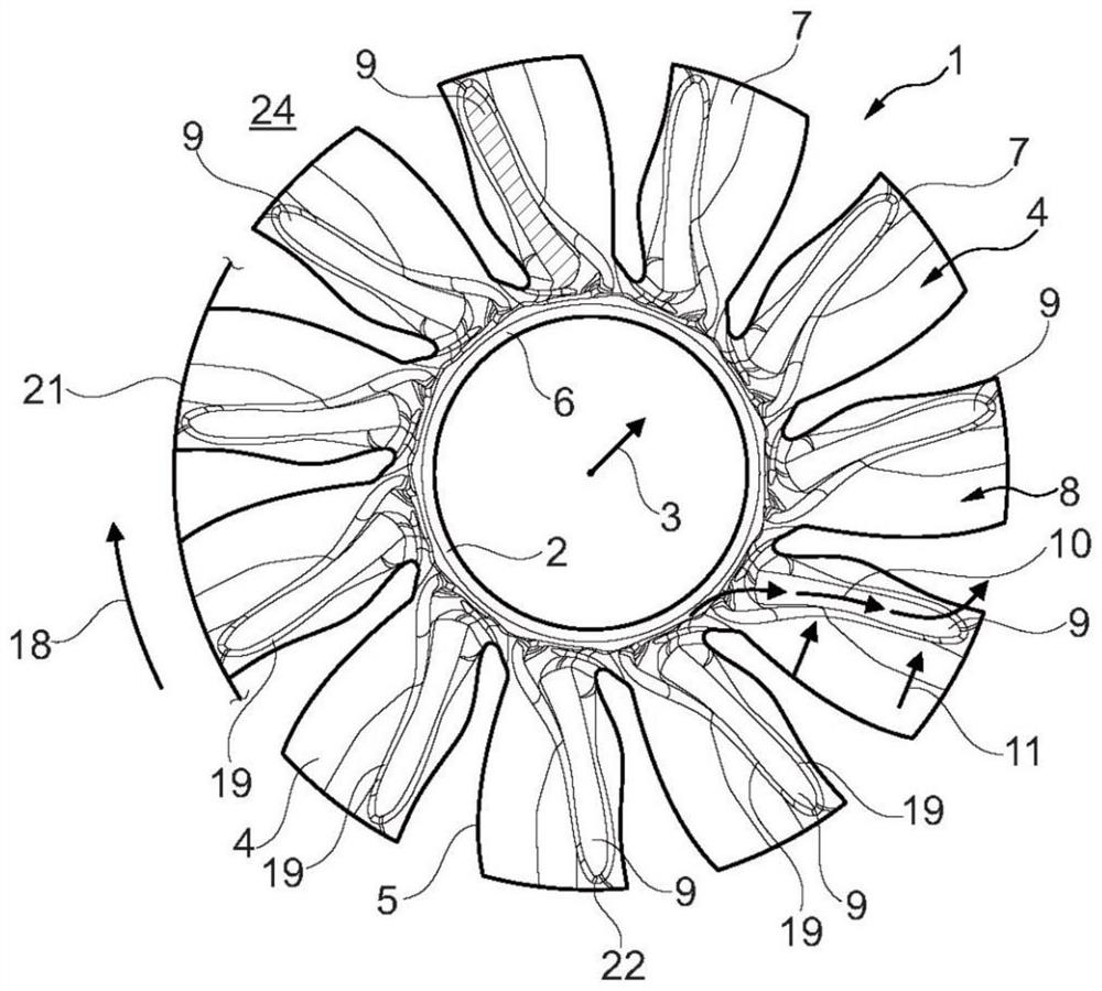
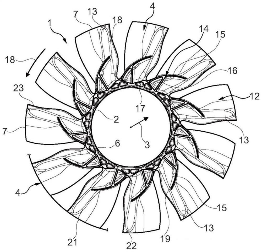
[0030] according to Figures 1 to 5 and 9 to 11, the fan impeller 1 according to the invention has a hub 2 and fan blades protruding from said hub in radial direction 3 . The fan blade 4 according to the invention has an S-shaped profile at the leading edge 5 (especially in contrast to Figure 5 ), and is formed thicker at the hub region 6 than at the fan blade tip 7. At the same time according to the present invention, a channel 9 is provided on the front side 8 of the corresponding fan blade 4 (see figure 1 , 3 , 6, 7 and 9 to 11), the channel is closer to the leading edge 5 at the hub side than at the fan blade tip 7 and therefore runs obliquely on the suction side or front face 8 of the fan blade 4 .

[0031] according to figure 1 , the channel 9 formed here is shown hatched on the fan blade 4 to illustrate its outline. It goes without saying here that such a channel 9 is arranged on each of the fan blades 4 . By means of such a channel 9 designed according to the in...


PUM


Abstract

The invention relates to a fan impleller (1) having a hub (2) and fan blades (4) projecting therefrom. It is essential to the invention that each fan blade (4) has an S-shaped profile at the leading edge (5); the fan blades (4) are thicker at the hub region (6) than at the fan blade tips (7); channels (9) are arranged on the front faces (8) of the fan blades (4), said channels extending obliquely on the front faces (8) of the fan blades (4). As a result, it is possible to achieve a high-power and stable fan impeller (1).

Description

technical field [0001] The invention relates to a fan wheel with a hub and fan blades protruding from the hub. Furthermore, the invention relates to a fan with such a fan wheel and a method for producing different such fan wheels. Background technique [0002] Universal fan wheels with a hub and fan blades protruding from said hub in radial direction are already widely known and are used, for example, on radiators of motor vehicles for cooling internal combustion engines. In addition to high fan power, a high (at least sufficient) stability of such fan wheels is always desired, especially when said fan wheels are mounted, for example, behind radiators and in engine compartments of motor vehicles. When in front of the internal combustion engine. Here, the fan performance is mainly determined by the shape of the fan blades, wherein a high fan performance cannot be achieved with fan blades of any size since the installation space required for this is not available. [0003] ...

Claims


Application Information

Patent Timeline
Patent Type & Authority Applications(China)
IPC IPC(8): F04D29/38F04D29/32
CPCF04D29/386F04D29/388F04D29/329F04D29/384F04D29/023F05D2240/303F04D29/326
Inventor 弗罗·斯蒂芬妮·拉尔庞
Owner MAHLE INT GMBH
Why Eureka
Try Eureka