Wing sleeve for laminar flow control technology flight test

A flight test and flow control technology, applied in the field of aerospace, can solve the problems of long development cycle and high cost, and achieve the effect of low cost, ensuring safety and maintaining aerodynamic characteristics

Pending Publication Date: 2021-06-25
NORTHWESTERN POLYTECHNICAL UNIV
View PDF0 Cites 0 Cited by
  • Summary
  • Abstract
  • Description
  • Claims
  • Application Information

AI Technical Summary

Problems solved by technology

Redesigning and manufacturing a complete flight test platform is the most direct way, but designing and manufacturing a complete flight test platform for laminar flow control technology from scratch has the disadvantages of long development cycle and high cost

Method used


Image

  • Wing sleeve for laminar flow control technology flight test
  • Wing sleeve for laminar flow control technology flight test
  • Wing sleeve for laminar flow control technology flight test

Examples


Embodiment 1

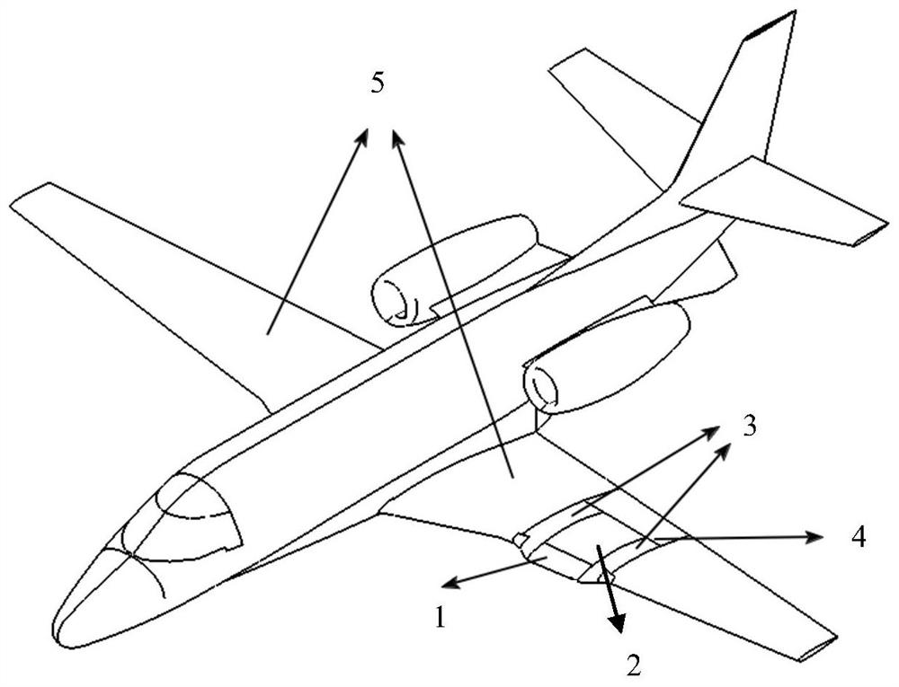
[0027] EXAMPLE 1. A wing sleeve for laminar flow control technology flight test, such as figure 1 As shown, including the laminar flow control wing, the laminar flow control wing set is provided with a replaceable front edge section 1, the test section 2, and the two transition segments 3, which can be replaced with the front edge section 1 and the test section 2 constitute a wing set effective test area. However, the replaceable front edge section 1 has the same exhibition length as the test section 2, which can be replaced with a leading edge section 1 using a smooth non-suction hole front edge section or a porous suction wall panel front edge section, and a smooth non-suction hole front edge section. Used to carry out the natural laminar flight test, the front edge section of the porous suction wall is used to perform a mixed layer flow control flight test, which can be replaced by flexible adjustment according to the purpose of the flight test, so that the wing is suitable for...


PUM


Abstract

The invention relates to the technical field of space flight and aviation, and discloses a wing sleeve for a laminar flow control technology flight test. The wing sleeve comprises a laminar flow control wing sleeve; the laminar flow control wing sleeve is provided with a replaceable leading edge section, a test section and two transition sections; the front part of the test section is connected with the replaceable leading edge section; the rear part of the test section is in smooth transition connection with a flight platform reference wing rear beam; the transition sections are in smooth connection with the wing sleeve effective test area and the flight platform reference wing. The front edge of the wing sleeve can be flexibly adjusted according to the flight test purpose, so that the wing sleeve is suitable for a natural / mixed laminar flow control flight test. The original aerodynamic characteristics of the aircraft platform can be maintained to the maximum extent, and the safety of the flight test platform is guaranteed. The upper airfoil laminar flow area of the effective test section area of the wing sleeve can be gradually changed between 0% c and 48% c under the designed test flight working condition and the natural laminar flow condition, and the flight test requirement for the purpose of comparing the natural laminar flow and the mixed laminar flow to control the transition inhibition effect can be met.

Description

Technical field [0001] The present invention relates to the field of aerospace agency, and in particular to a wing sleeve for laminar flow control technology flight test. Background technique [0002] For typical civil jet passenger aircraft, frictional resistance is almost about 50% of total resistance, while laminar flow technology can greatly reduce the frictional resistance of the wing, significant ground by realizing a considerable laminar flow in the wing surface. Improve the aerodynamic efficiency of the whole machine. Therefore, layer flow restriction techniques are considered to be one of the most likely applied in the future to new technologies in civil airliner design. [0003] TS wave loss is a very important turning mechanism existing in the surface flow of the aircraft. For wings having a small leading edge (usually after the inclusions are not more than 15 °), the laminar flow is stable by TS wave. leading. Therefore, a civilian passenger plane that is not more tha...

Claims


Application Information

Patent Timeline
IPC IPC(8): B64F5/60
CPCB64F5/60
Inventor 杨体浩史亚云白俊强钟海
Owner NORTHWESTERN POLYTECHNICAL UNIV
Why Eureka
Try Eureka