
An integrated spot welding equipment for smart meter terminals and its use method

A technology of spot welding equipment and smart meters, applied in welding equipment, auxiliary welding equipment, welding/cutting auxiliary equipment, etc., can solve the problem that the production speed of smart meters cannot meet market demand, the labor intensity of staff is high, and the efficiency of electric welding operations is low. problems, achieve the effect of realizing double-sided welding operations, responding to market changes, and reducing labor intensity

Active Publication Date: 2021-12-10
浙江能兴电气科技有限公司
View PDF0 Cites 0 Cited by
  • Summary
  • Abstract
  • Description
  • Claims
  • Application Information

AI Technical Summary

Problems solved by technology

[0002] The smart meter is the smart terminal of the smart grid. In addition to the basic power consumption measurement function of the traditional power meter, in order to adapt to the use of smart grid and new energy, it also has two-way multi-rate metering functions, user-end control functions, and various Intelligent functions such as two-way data communication function of data transmission mode, anti-stealing function, etc., smart meters represent the development direction of energy-saving smart grid end-user intelligent terminals in the future; The original parts need to be spot-welded. Traditional electric welding is mostly manual electric welding. The efficiency of electric welding is low, which leads to the production speed of smart meters that cannot meet the market demand, and the labor intensity of the staff is relatively high; the electric welding equipment in the prior art Spot welding can only be performed on one side, but double-sided welding is required for circuit board welding, and the welding work is cumbersome

Method used


Image

  • An integrated spot welding equipment for smart meter terminals and its use method
  • An integrated spot welding equipment for smart meter terminals and its use method
  • An integrated spot welding equipment for smart meter terminals and its use method

Examples


Embodiment Construction

[0066] The following will clearly and completely describe the technical solutions in the embodiments of the present invention with reference to the accompanying drawings in the embodiments of the present invention. Obviously, the described embodiments are only some, not all, embodiments of the present invention. Based on the embodiments of the present invention, all other embodiments obtained by persons of ordinary skill in the art without creative efforts fall within the protection scope of the present invention.

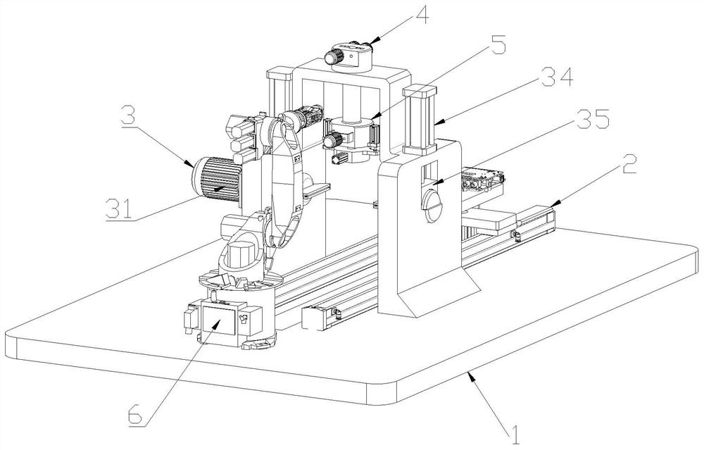
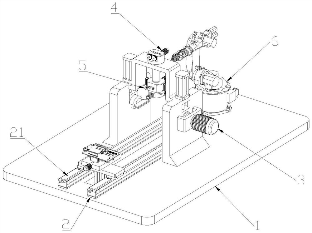
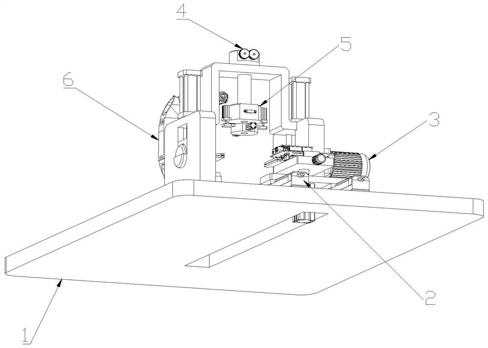
[0067] An integrated spot welding equipment for smart meter terminals, the spot welding equipment includes a support frame 1, and the support frame 1 is provided with a feeding part 2 for the transmission of electric meter parts, such as figure 1 , figure 2 , image 3 As shown, the support frame 1 is provided with a rotating part 3, the support frame 1 is provided with a transmission part 4 for terminal transmission, the lower part of the transmission part 4 is p...


PUM


Abstract

The invention discloses an intelligent electric meter terminal integrated spot welding device and a using method thereof. The spot welding device includes a support frame, on which a feeding part for electric meter parts transmission is arranged, on the support frame is provided a rotating part, and on the support frame There is a transmission part for terminal transmission on the upper part, a peeling part for terminal peeling is provided under the transmission part, and a mechanical arm for spot welding is provided on the support frame; the method of use includes the following steps: terminal feeding, extrusion cutting, Stripping, transfer, clamping, terminal transfer, soldering. The contact point is welded by the mechanical arm, replacing the traditional manual electric welding operation, which improves the efficiency of the welding operation, meets market demand, responds to market changes in a timely manner, and reduces the labor intensity of the staff; the rotation of the circuit board is realized through the rotating parts. Double-sided welding operation simplifies the process.

Description

technical field [0001] The invention relates to the field of electric meter production, in particular to an intelligent electric meter terminal integrated spot welding device and a use method. Background technique [0002] The smart meter is the smart terminal of the smart grid. In addition to the basic power consumption measurement function of the traditional power meter, in order to adapt to the use of smart grid and new energy, it also has two-way multi-rate metering functions, user-side control functions, and various Intelligent functions such as two-way data communication function of data transmission mode, anti-stealing function, etc., smart meters represent the development direction of energy-saving smart grid end-user intelligent terminals in the future; The original parts need to be spot welded. Traditional electric welding is mostly manual electric welding. The efficiency of electric welding is low, which leads to the production speed of smart meters not meeting th...

Claims


Application Information

Patent Timeline
Patent Type & Authority Patents(China)
IPC IPC(8): B23K37/00B23K37/02B23K37/047G01R11/04B23K101/42
CPCB23K37/00B23K37/047B23K37/0252G01R11/04B23K2101/42
Inventor 夏伟刘雷沈学东
Owner 浙江能兴电气科技有限公司
Learn More