Electronic lock structure suitable for railway locomotive

A technology for railway locomotives and electronic locks, applied in electric locks, vehicle locks, building locks, etc., can solve the problems of door locks that cannot be opened, inconvenient to use, and inconvenience, etc., to solve the problems of easy power failure, avoid easy omission, and strong practicability Effect

Pending Publication Date: 2021-06-22
ZHUZHOU GUANGYI ELECTRONICS TECH
View PDF11 Cites 0 Cited by
  • Summary
  • Abstract
  • Description
  • Claims
  • Application Information

AI Technical Summary

Problems solved by technology

[0002] At present, the lock body structure mainly includes electronic locks and mechanical locks. Among them, when the mechanical lock is in use, if the key is accidentally lost, the entire door lock needs to be removed and replaced, while the electronic lock needs to ensure its power. If you go out urgently when there is no power, and you cannot charge it in time, it will easily cause the door lock to fail to open, which is inconvenient to use
[0003] Especially when it is used on the locomotive door body, since multiple doors of the locomotive usually use the same type of key, when the key is missing, multiple door bodies must be replaced at the same time, and battery replacement also requires multiple door bodies to be replaced at the same time, which is extremely inconvenient

Method used


Image

  • Electronic lock structure suitable for railway locomotive
  • Electronic lock structure suitable for railway locomotive
  • Electronic lock structure suitable for railway locomotive

Examples


Embodiment Construction

[0032] In order to make the object, technical solution and advantages of the present invention clearer, the present invention will be further described in detail below in conjunction with the accompanying drawings and embodiments. It should be understood that the specific embodiments described here are only used to explain the present invention, and are not intended to limit the present invention, that is, the described embodiments are only some of the embodiments of the present invention, but not all of the embodiments. The components of the embodiments of the invention generally described and illustrated in the figures herein may be arranged and designed in a variety of different configurations.

[0033] Accordingly, the following detailed description of the embodiments of the invention provided in the accompanying drawings is not intended to limit the scope of the claimed invention, but merely represents selected embodiments of the invention. Based on the embodiments of the...


PUM


Abstract

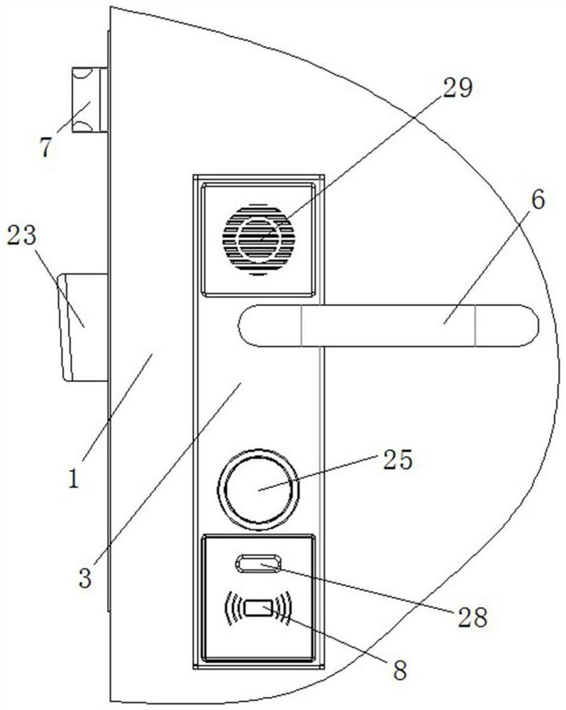
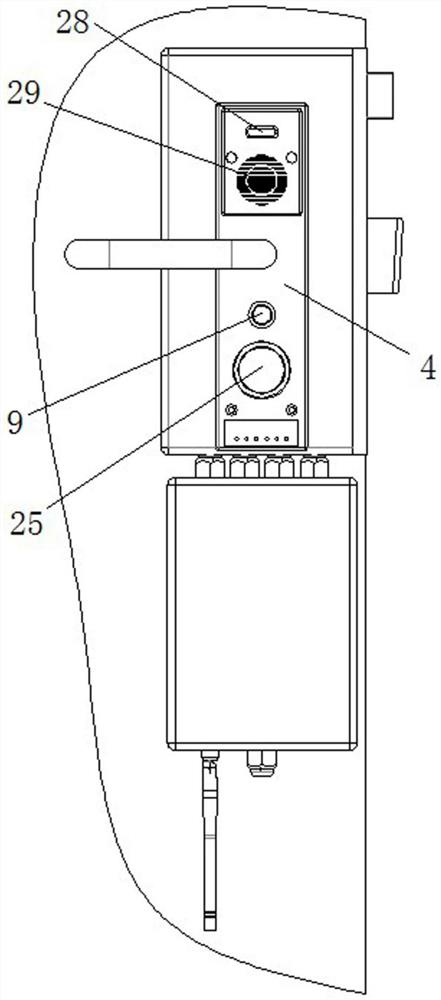
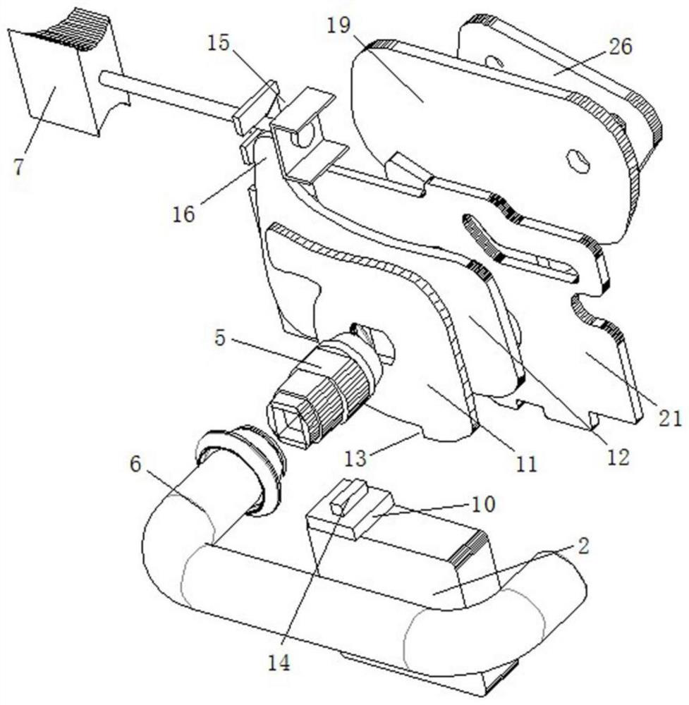
The invention discloses an electronic lock structure suitable for a railway locomotive. The electronic lock structure comprises a lock shell, wherein a control box is arranged in the lock shell, an outer panel and an inner panel are arranged at the two ends of the lock shell respectively, a spring bolt is arranged on the side wall of the lock box, and a control component in transmission connection with the spring bolt is arranged on a handle shaft; a brake component is arranged on the control box and is suitable for clamping and fixing the handle shaft; a magnetic card induction area electrically connected to the control box is arranged on the outer panel; and a key hole is further formed in the outer panel, a mechanical switch matched with the key hole is arranged in the control box, and the mechanical switch is suitable for controlling opening and closing of the brake component. According to the scheme, through the mode of combining electronic unlocking and mechanical unlocking, compared with a traditional electronic door lock and a traditional mechanical door lock, the scheme combines the advantages of the electronic door lock and the mechanical door lock, the problem that the electronic door lock is prone to power failure can be solved, meanwhile, the situation that a key of the mechanical door lock is prone to missing can be avoided, and the practicability is high.

Description

technical field [0001] The invention relates to the technical field of door lock structures, in particular to an electronic lock structure suitable for railway locomotives. Background technique [0002] At present, the lock body structure mainly includes electronic locks and mechanical locks. Among them, when the mechanical lock is in use, if the key is accidentally lost, the entire door lock needs to be removed and replaced, while the electronic lock needs to ensure its power. If you go out urgently when there is no electricity and cannot charge in time, it will easily cause the situation that the door lock cannot be opened, which is inconvenient to use. [0003] Especially when it is used on the locomotive door body, since multiple doors of the locomotive usually use the same type of key, when the key is missing, multiple door bodies must be replaced at the same time, and battery replacement also requires multiple door bodies to be replaced at the same time, which is extre...

Claims


Application Information

Patent Timeline
IPC IPC(8): E05B85/10E05B85/02E05B85/22E05B79/06E05B81/08E05B81/66E05B81/72E05B81/90E05B83/36
CPCE05B85/10E05B85/02E05B85/22E05B79/06E05B81/08E05B81/66E05B81/72E05B81/90E05B83/363
Inventor 陈侠飞
Owner ZHUZHOU GUANGYI ELECTRONICS TECH
Why Eureka
Try Eureka