
An electrical monitoring device suitable for true triaxial loading and its application method

A monitoring device, true triaxial technology, applied in the direction of measuring devices, using stable tension/pressure testing material strength, instruments, etc., can solve problems such as difficult and accurate data, on-site environment simulation deviation, inconvenient installation, etc., to avoid being affected Compression deformation damage, easy safe displacement, and the effect of improving flatness

Active Publication Date: 2021-11-16
CHINA UNIV OF MINING & TECH
View PDF13 Cites 0 Cited by
  • Summary
  • Abstract
  • Description
  • Claims
  • Application Information

AI Technical Summary

Problems solved by technology

However, in this operation mode, it is easy to change the physical structure and chemical properties of the coal rock, and destroy the integrity of the coal rock mass, which will cause a large deviation in the simulation of the on-site environment.
Moreover, at present, when measuring the electrical characteristics of coal and rock mass under uniaxial or true triaxial conditions, due to the inconvenience of installation, most of them use a small number of probes or electrodes for monitoring, and the amount of data obtained is not much, so it is difficult to comprehensively hydraulically compress coal and rock mass Study on the changing characteristics of cracking process
Chinese patent CN105716954A discloses a crack morphology electrical monitoring method for hydraulic fracturing simulation experiments. When cement is poured, a plurality of conductive graphite rod arrays are added. The change of resistivity and resistance can judge the development of cracks, but this method makes the electrode unable to be recycled, resulting in waste of materials, and the measurement method is relatively traditional, so it is difficult to obtain accurate data efficiently

Method used


Image

  • An electrical monitoring device suitable for true triaxial loading and its application method
  • An electrical monitoring device suitable for true triaxial loading and its application method
  • An electrical monitoring device suitable for true triaxial loading and its application method

Examples


Embodiment Construction

[0037] The following will clearly and completely describe the technical solutions in the embodiments of the present invention with reference to the accompanying drawings in the embodiments of the present invention. Obviously, the described embodiments are only some, not all, embodiments of the present invention. Based on the embodiments of the present invention, all other embodiments obtained by persons of ordinary skill in the art without making creative efforts belong to the protection scope of the present invention.

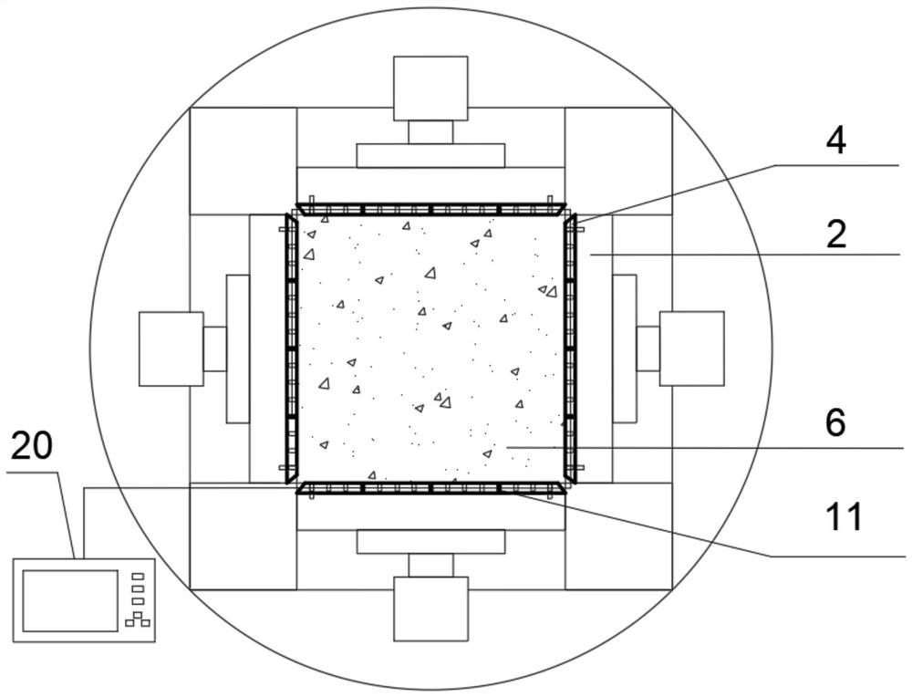
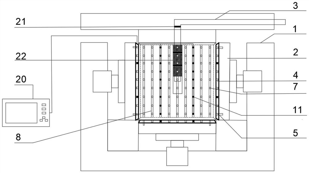
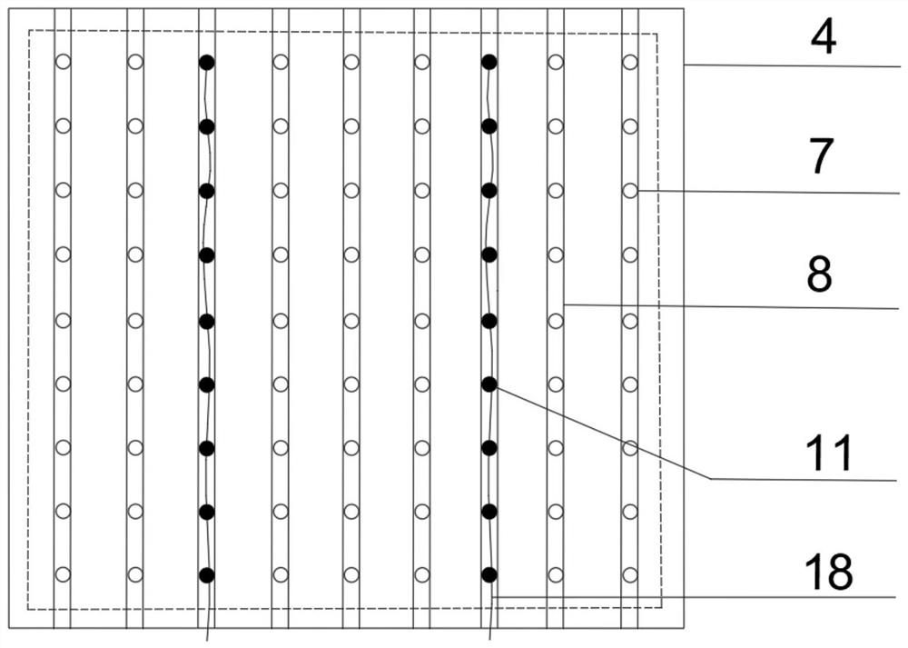
[0038] Embodiment 1: The electrical detection experiment of rock sample 6 under the condition of true triaxial loading and failure process, such as figure 1 , Figure 3-Figure 6 As shown, select a rock sample 6 with a size of 500*500*500mm; determine the length, width, and thickness of the electrode mounting plate 4 according to the size of the rock sample 6 to be 500*500*20mm, and determine that 4 electrode mounting plates 4 are respectively installed on The...


PUM

PropertyMeasurementUnit
thicknessaaaaaaaaaa

Abstract

The invention discloses an electrical monitoring device suitable for true three-axis loading, which includes an electrode mounting plate fixed on the loading plate, and a plurality of threaded holes for installing electrode bodies and uniformly distributed in a rectangular array are opened on the electrode mounting plate The side of the electrode mounting plate attached to the loading plate is provided with a number of slots for connecting the ends of the threaded holes in the same row or in the same line in series. The two ends of the slots extend to the edge of the electrode mounting plate respectively. This device provides a new type of electrode It is more convenient to install and replace, and at the same time, the selection of the installation position of the electrode body is more flexible. The device and method can be used to monitor the electrical change characteristics of the rock sample in the whole process of loading and failure in an all-round way.

Description

technical field [0001] The invention relates to the field of indoor mechanics and electrical characteristics experiments of coal and rock mass, in particular to an electrical monitoring device suitable for true triaxial loading and a use method thereof. Background technique [0002] At present, underground geotechnical engineering has been involved in underground mining, natural gas and oil and other energy sources, and it also affects the construction of tunnels and underground caverns. Deep rock and soil bear forces in three orthogonal directions. Under axial loading conditions, the ground stress can be truly simulated, which are the maximum principal stress, medium principal stress and small principal stress. Under any mining conditions, the stress state of the underground rock and soil will be disturbed, the internal structure of the rock will change, and its electrical characteristics will also change. For example, the development of cracks will lead to an increase in r...

Claims


Application Information

Patent Timeline
Patent Type & Authority Patents(China)
IPC IPC(8): G01N3/06G01N3/08
CPCG01N3/066G01N3/08G01N2203/0019G01N2203/0067G01N2203/0256G01N2203/0617
Inventor 李楠赵辉燕满月蔡超陈鹏李志怀
Owner CHINA UNIV OF MINING & TECH
Learn More