Auxiliary turning device for daily care of paralyzed patients that can rotate and reduce compression
A paralyzed patient, rotating technology, applied in hospital beds, medical science, hospital equipment, etc., can solve the problems of wasting manpower, necrosis, and laborious caregivers, and achieve the effect of reducing manpower waste, simple use, and meeting the needs of daily care.
- Summary
- Abstract
- Description
- Claims
- Application Information
AI Technical Summary
Problems solved by technology
Method used
Image

Examples
Embodiment 1
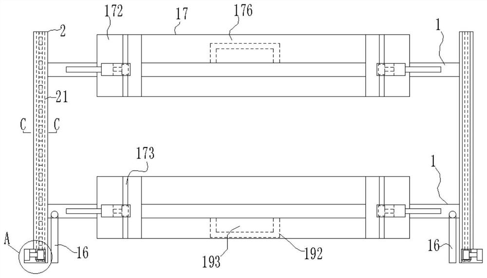
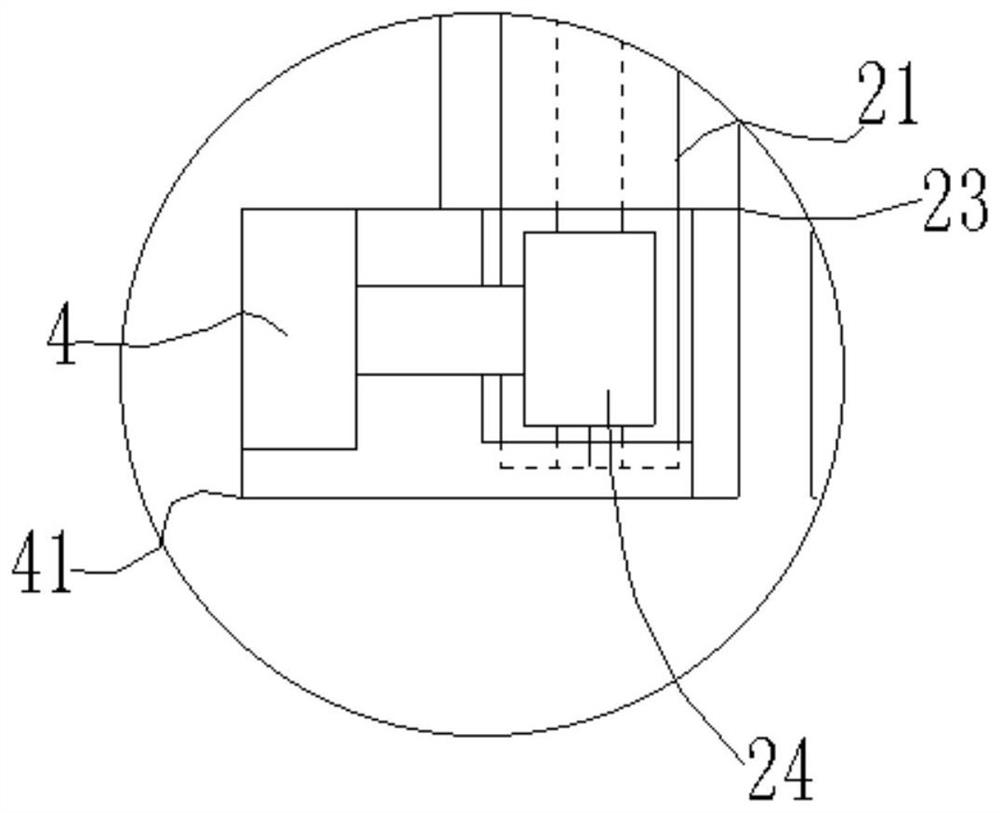
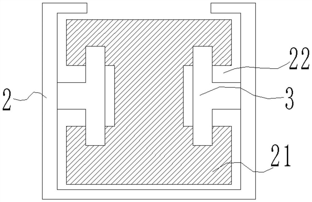
[0029] like figure 1 As shown in the figure, the auxiliary turning device for daily nursing of paralyzed patients, which is rotary and can reduce compression, includes nursing bed 1, annular shell 2, sliding mechanism 3, motor 1 4, two annular shells 2, and two nursing beds 1. The two nursing beds 1 are movably connected laterally between the two annular shells 2, such as image 3 As shown, each annular shell 2 is provided with a rotating gear ring 21 in the middle, and the two sides of the rotating gear ring 21 are provided with sliding grooves 22, and the sliding groove 22 and the annular shell 2 are rotatably connected by a sliding mechanism 3, such as figure 2 As shown, there is a transmission port 23 under the front side of the annular shell 2, the motor one 4 is fixed on the front side of the transmission port 23, the gear one 24 is fixedly installed on the transmission shaft of the motor one 4, and the gear one 24 is connected with the transmission port 23 through the ...
Embodiment 2
[0031] like figure 1 As shown in the figure, the auxiliary turning device for daily nursing of paralyzed patients, which is rotary and can reduce compression, includes nursing bed 1, annular shell 2, sliding mechanism 3, motor 1 4, two annular shells 2, and two nursing beds 1. The two nursing beds 1 are movably connected laterally between the two annular shells 2, such as image 3 As shown, a rotating gear ring 21 is provided in the middle of each annular shell 2, and sliding grooves 22 are provided on both sides of the rotating gear ring 21. The sliding groove 22 and the annular shell 2 are rotatably connected by a sliding mechanism 3. figure 2 As shown, there is a transmission port 23 under the front side of the annular shell 2, the motor one 4 is fixed on the front side of the transmission port 23, the gear one 24 is fixedly installed on the transmission shaft of the motor one 4, and the gear one 24 is connected with the transmission port 23 through the transmission port 2...
Embodiment 3
[0035] like figure 1 As shown in the figure, the auxiliary turning device for daily nursing of paralyzed patients, which is rotary and can reduce compression, includes nursing bed 1, annular shell 2, sliding mechanism 3, motor 1 4, two annular shells 2, and two nursing beds 1. The two nursing beds 1 are movably connected laterally between the two annular shells 2, such as image 3 As shown, each annular shell 2 is provided with a rotating gear ring 21 in the middle, and the two sides of the rotating gear ring 21 are provided with sliding grooves 22, and the sliding groove 22 and the annular shell 2 are rotatably connected by a sliding mechanism 3, such as figure 2 As shown, there is a transmission port 23 under the front side of the annular shell 2, the motor one 4 is fixed on the front side of the transmission port 23, the gear one 24 is fixedly installed on the transmission shaft of the motor one 4, and the gear one 24 is connected with the transmission port 23 through the ...
PUM
 Abstract
Description
Claims
Application Information
 - R&D Engineer
- R&D Manager
- IP Professional
- Industry Leading Data Capabilities
- Powerful AI technology
- Patent DNA Extraction
Browse by: Latest US Patents, China's latest patents, Technical Efficacy Thesaurus, Application Domain, Technology Topic.
© 2024 PatSnap. All rights reserved.Legal|Privacy policy|Modern Slavery Act Transparency Statement|Sitemap