
Special rotary refueling structure for replacing moving body of control rod assembly

A moving body and control rod technology, which is applied in the control of nuclear reactions, reduction of greenhouse gases, reactor fuel elements, etc., to achieve the effects of simple operation, easy cleaning and drying, and avoiding slippage.

Active Publication Date: 2021-05-28
CHINA INSTITUTE OF ATOMIC ENERGY
View PDF8 Cites 0 Cited by
  • Summary
  • Abstract
  • Description
  • Claims
  • Application Information

AI Technical Summary

Problems solved by technology

[0005] Currently there is no special tool for refueling that can be used to replace the moving body of the control rod and the outer sleeve of the control rod

Method used


Image

  • Special rotary refueling structure for replacing moving body of control rod assembly
  • Special rotary refueling structure for replacing moving body of control rod assembly
  • Special rotary refueling structure for replacing moving body of control rod assembly

Examples


Embodiment Construction

[0035] The present invention will be described in detail below in conjunction with the accompanying drawings and embodiments.

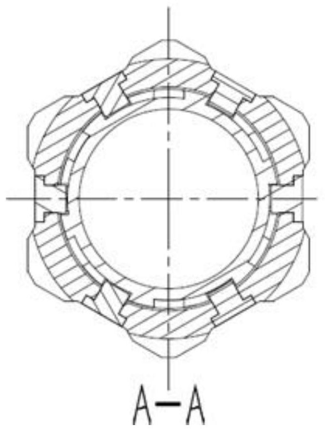
[0036] Such as figure 1 As shown, the present invention provides a special rotary refueling structure for replacing the moving body of the control rod assembly, including a casing assembly; the moving body can at least partially extend into the casing assembly, and the moving body and the casing assembly Through the action of the locking structure, the moving body and the jacket assembly can move relative to each other or be relatively stationary in the axial direction.

[0037] Such as figure 1 As shown, the jacket assembly includes an upper transition head 8 , an outer sleeve 9 , a lower transition head 14 and a pin 15 fixedly connected in sequence. The locking part is a pin 7 arranged on the upper transition head 8 . The pin 7 is used to cooperate with the locking groove of the mobile body, so as to realize the locking and unlocking functions of...


PUM


Abstract

The invention relates to a special rotary refueling structure for replacing a moving body of a control rod assembly. The special rotary refueling structure comprises an outer sleeve assembly, wherein the moving body at least can partially extend into the outer sleeve assembly, and the moving body and the outer sleeve assembly can relatively move or relatively stand still in an axial direction through the action of a locking structure; the locking structure comprises a locking part arranged on the outer sleeve assembly and a locking groove formed in the moving body; the locking groove is L-shaped and comprises a transverse groove and a vertical groove which communicate with each other; during locking, the locking part ascends to a limited position from the vertical groove, then rotates relative to the moving body and enters the transverse groove; and during unlocking, the locking part rotates from the transverse groove to the moving body reversely and relatively to a limited position and then descends along the vertical groove. The special rotary refueling structure of the invention has the following beneficial effects: under the operation of a refueling machine in a reactor core, the outer sleeve assembly can be reliably locked and unlocked with the moving body, and the outer sleeve assembly can participate in the whole refueling process along with the control rod moving body.

Description

technical field [0001] The invention belongs to the field of nuclear industry, and in particular relates to a special rotary refueling structure for replacing a moving body of a control rod assembly. Background technique [0002] The China Experimental Fast Reactor is the first sodium-cooled fast reactor in China. The shape of the control rod assembly is the same as that of the fuel assembly, and its structure is an integrated structure. The refueling process of the control rod assembly is the same as that of the fuel assembly. [0003] The internal control rod assembly of the 600MW demonstration fast reactor is improved on the basis of the Chinese experimental fast reactor structure and adopts a split structure. The control rod assembly is composed of two parts: the control rod moving body and the control rod outer sleeve. Adopting this structure can effectively reduce the The height of the container reduces the amount of nuclear waste while improving the utilization of mat...

Claims


Application Information

Patent Timeline
Patent Type & Authority Applications(China)
IPC IPC(8): G21C19/10G21C7/08
CPCG21C19/10G21C7/08Y02E30/30
Inventor 夏凡王浩仲苏喜平刘川川谷继品王明政吴水金杨孔雳杨勇于团结徐宝玉刘志芳靳峰雷邓夏
Owner CHINA INSTITUTE OF ATOMIC ENERGY
Learn More