
Drilling machine for machining and using method thereof

A technology of mechanical processing and drilling machine, applied in the direction of boring/drilling, metal processing equipment, drilling/drilling equipment, etc., can solve the problems of tediousness, large device size, inability to use various bottom surfaces, etc. , to achieve the effect of good practicability and accuracy

Pending Publication Date: 2021-05-28
赣州市恒邦金属制品有限公司
View PDF0 Cites 0 Cited by
  • Summary
  • Abstract
  • Description
  • Claims
  • Application Information

AI Technical Summary

Problems solved by technology

[0003] In common drilling machines for mechanical processing, the device is large and inconvenient to move, which is not conducive to on-site use during construction site operations, and cannot use various bottom surfaces. At the same time, the drill bit in the drilling machine cannot adjust the angle , it is not conducive to the precise drilling of the drill bit, and the existing drilling machine also has relatively cumbersome problems in the height adjustment of the drill bit

Method used


Image

  • Drilling machine for machining and using method thereof
  • Drilling machine for machining and using method thereof
  • Drilling machine for machining and using method thereof

Examples


Embodiment 1

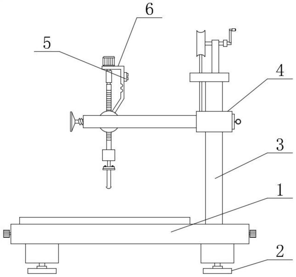
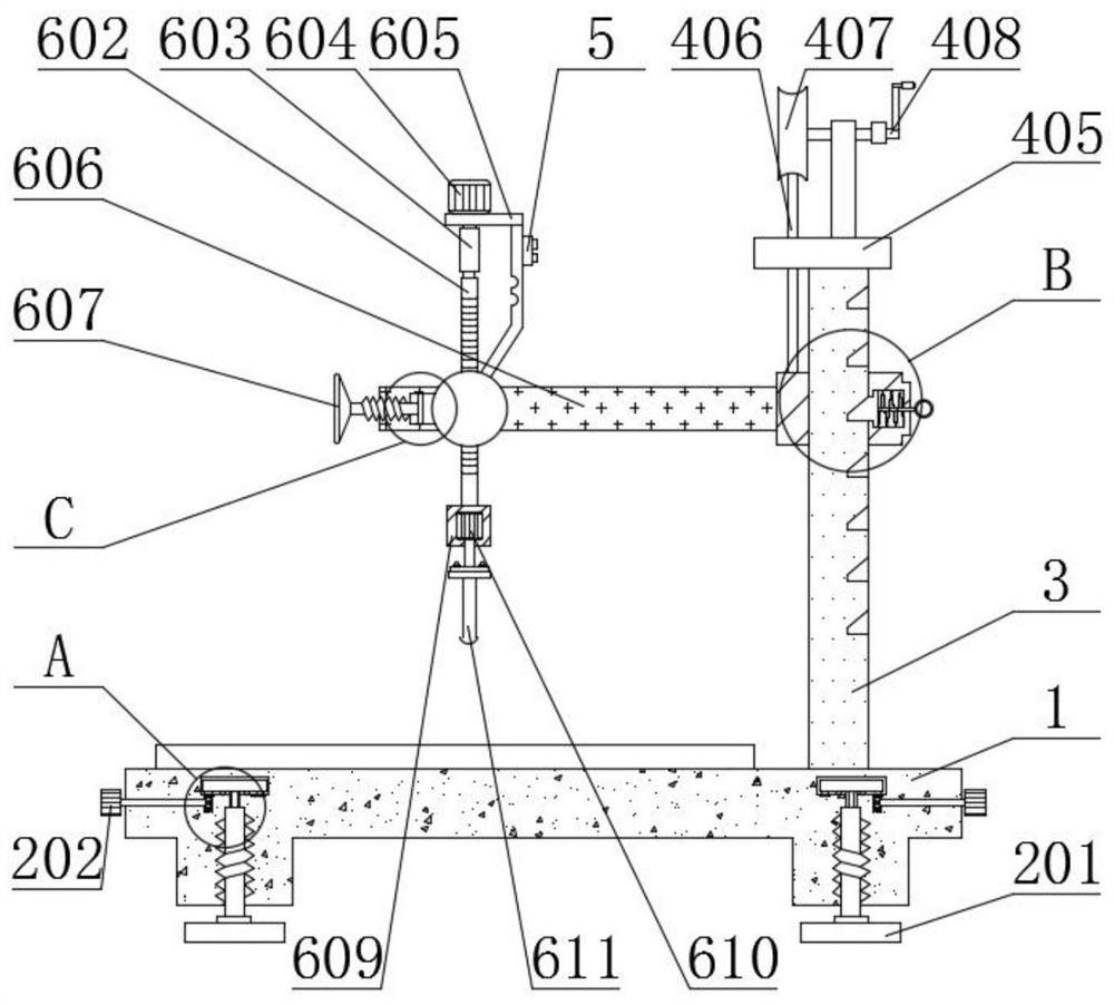
[0032] see Figure 1-7 , the present invention provides a technical solution:

[0033] A drilling machine for mechanical processing, comprising a base 1 and a controller 5, a base flatness adjustment mechanism 2 is provided at the inner four corners of the base 1, a support column 3 is fixedly connected to the right side of the top of the base 1, and the outer side of the support column 3 A height adjustment mechanism 4 is provided. The height adjustment mechanism 4 includes a horizontal plate 606. The left end of the horizontal plate 606 is provided with a drilling mechanism 6. The base flatness adjustment mechanism 2 includes a rotating hand 202 and a turntable 203. The rotation of the turntable 203 is set on the bottom of the base 1. On the inner side, the bottom end of the turntable 203 is fixedly connected with a gear ring 205, and the central position of the bottom end of the turntable 203 is fixedly connected with an inner rod 206. 208, the inner side of the base 1 is ...

Embodiment 2

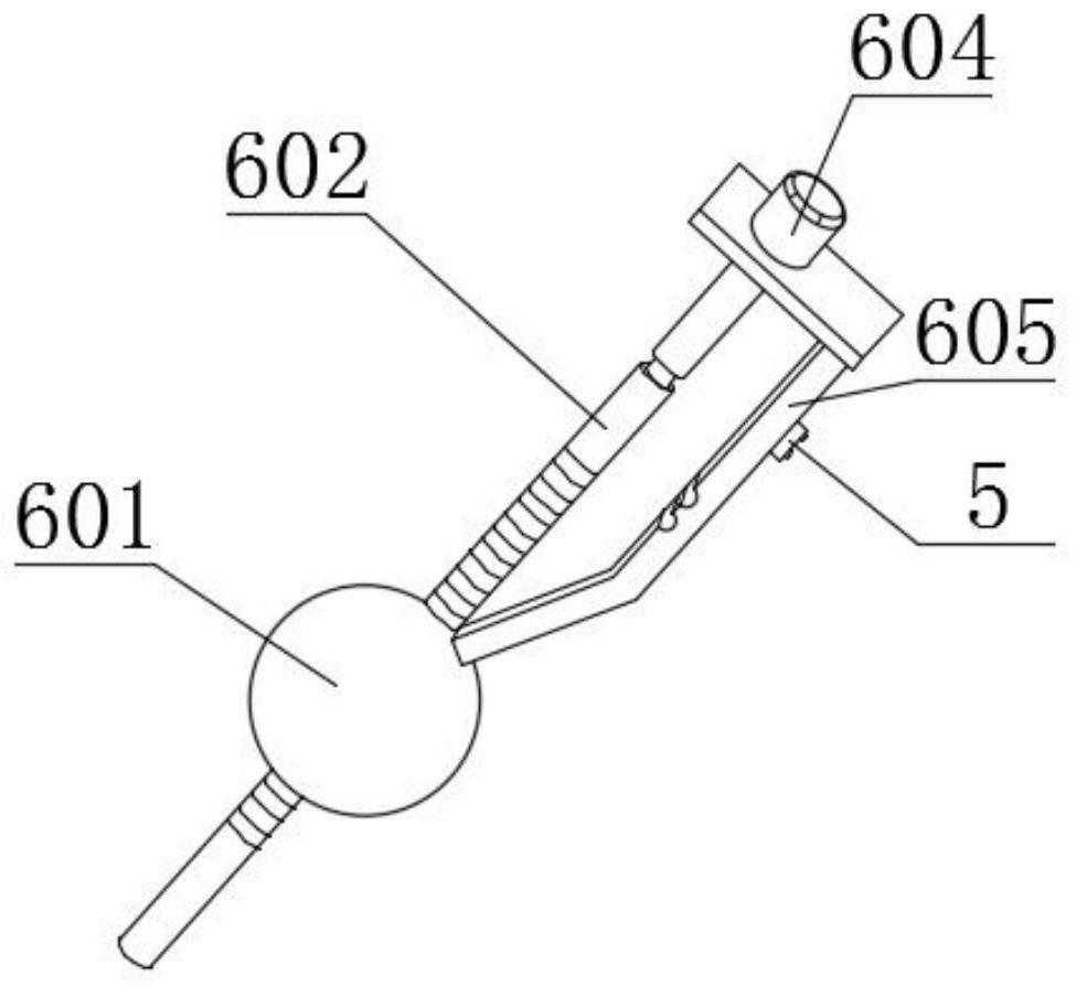
[0038] Workflow: The same parts in this embodiment as in Embodiment 1 will not be repeated, the difference is that the present invention can also realize the adjustment of the drilling angle, when adjusting, the staff can hold the support frame 605 with their hands, Rotate the compression screw 607, and the compression screw 607 will drive the rubber pad 608 to rotate left or right during the rotation process. When the rubber pad 608 moves to the left for a certain distance, the staff can adjust the support frame 605 and press Under the action of the rotating ball 601, the angle of the drilling head 611 is changed. After adjusting to the required angle, turn the compression screw 607 again to keep the rubber pad 608 and the rotating ball 601 in close contact, thereby realizing counter-rotating balls. The fixing of the angle between 601 and drilling head 611 has good practicability. After fixing, the staff can control the first motor 604 to rotate through the controller 5, and t...


PUM


Abstract

The invention relates to the technical field of drilling machines, in particular to a drilling machine for machining. The drilling machine comprises a base and a controller, base flatness adjusting mechanisms are arranged at the four corners of the inner side of the base, a supporting column is fixedly connected to the right side of the top end of the base, and a height adjusting mechanism is arranged on the outer side of the supporting column. The height adjusting mechanism comprises a transverse plate, a drilling mechanism is arranged at the left end of the transverse plate, the four corners of the base can be adjusted through the base flatness adjusting mechanisms, leveling of the drilling machine can be achieved by referring to an external horizontal ruler, the accuracy during machining is guaranteed, a rotating handle is rotated, a rotating disc rotates to drive an inner rod to rotate, the inner rod rotates to drive an outer rod to rotate, the outer rod rotates to move upwards or downwards under the action of threads and a threaded grooves, and the outer rod drives a bottom plate to move upwards or downwards, so that height adjustment of the four corners of the base is achieved, and the drilling machine is in a horizontal state.

Description

technical field [0001] The invention relates to the technical field of drilling machines, in particular to a drilling machine for machining and a use method thereof. Background technique [0002] Drilling machine refers to the general name of machinery and equipment that leaves cylindrical holes or holes on the target by means of rotary cutting or rotary extrusion with a tool that is harder and sharper than the target. machine, drilling machine, through hole machine, etc. To achieve the desired effect by drilling precision parts, any kind of machine or part cannot be made without holes. To connect parts, screw holes, pin holes or rivet holes of various sizes are required. Fixing the transmission parts requires various mounting holes, and the machine parts themselves also have many various holes. [0003] In common drilling machines for mechanical processing, the device is large and inconvenient to move, which is not conducive to on-site use during construction site operati...

Claims


Application Information

Patent Timeline
Patent Type & Authority Applications(China)
IPC IPC(8): B23B39/00B23B47/00B23B47/20B23Q1/25
CPCB23B39/00B23B47/00B23Q1/25B23Q5/40
Inventor 刘运辉
Owner 赣州市恒邦金属制品有限公司
Learn More