Data output method, device and system
A technology of an output device and an output method, which is applied in the field of data transmission, can solve problems such as data sampling errors and difficulty in satisfying timing constraints at the receiving end, and achieve the effects of correct data sampling, dynamic adjustment of phase relationship, and stable data transmission
- Summary
- Abstract
- Description
- Claims
- Application Information
AI Technical Summary
Problems solved by technology
Method used
Image
Examples
no. 1 example
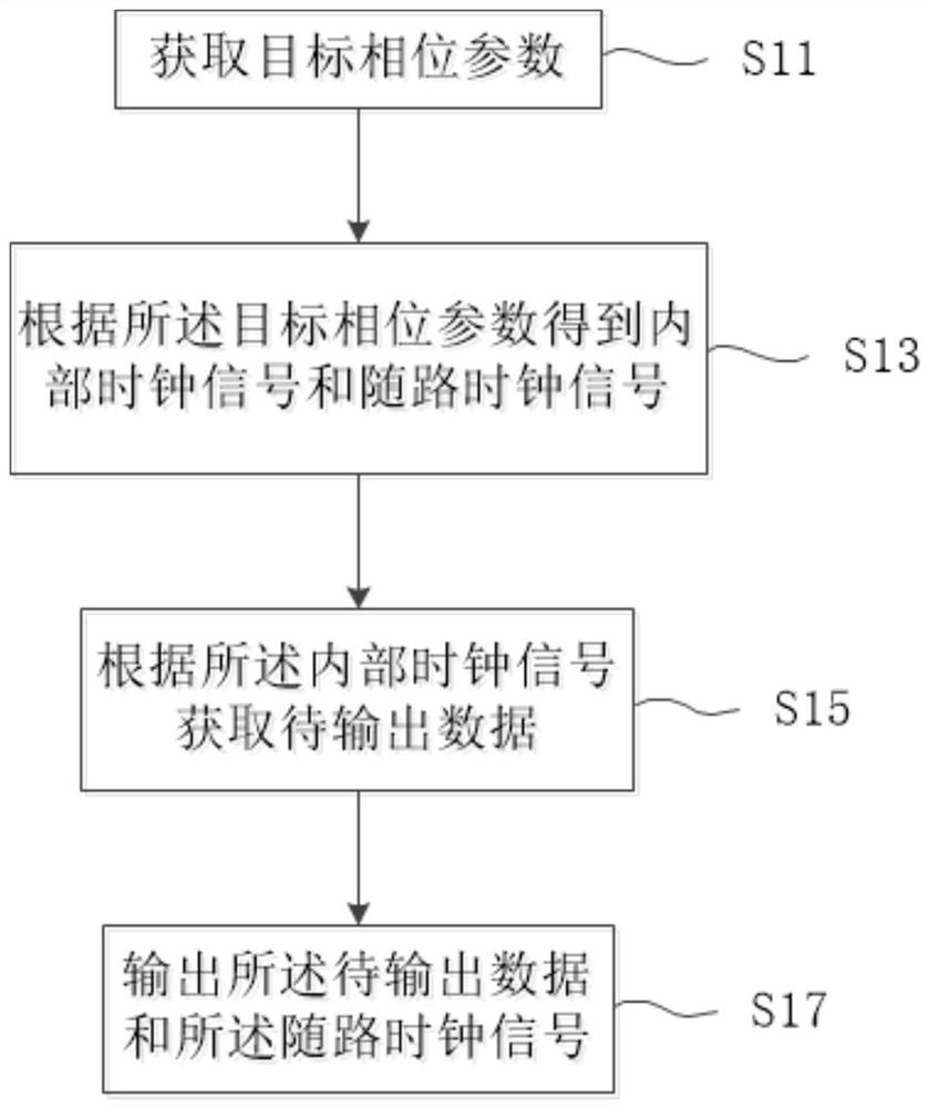
[0040] see figure 1 and figure 2, a data output method proposed in the first embodiment of the present application, which can be executed by a programmable logic device. The method, for example, includes steps S11 to S17.
[0041] Step S11: Acquiring target phase parameters;
[0042] Step S13: Obtain an internal clock signal and an associated clock signal according to the target phase parameter;
[0043] Step S15: Obtain data to be output according to the internal clock signal; and
[0044] Step S17: Outputting the data to be output and the associated clock signal.
[0045] In step S11, acquiring the target phase parameter may further include: the data sending device receives a phase adjustment command, and parses the phase adjustment command to obtain the target phase parameter. Such as figure 2 As shown, the dotted line box represents a data sending device. Optionally, the data sending device can be used to convert the video source signal into a source synchronous in...
no. 2 example
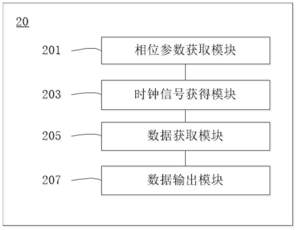
[0056] Such as figure 2 As shown, the second embodiment of the present application provides a data output device. The data output device 20 includes: a phase parameter acquisition module 201 , a clock signal acquisition module 203 , a data acquisition module 205 and a data output module 207 .
[0057] Wherein, the phase parameter acquisition module 201 is used to acquire target phase parameters. The clock signal obtaining module 203 is used to obtain an associated clock signal and an internal clock signal according to the target phase parameter. The data acquisition module 205 is configured to acquire data to be output according to the internal clock signal. The data output module 207 is used to output the data to be output and the associated clock.
[0058] Further, the clock signal obtaining module 203 is specifically configured to: adjust the phase of the current clock signal according to the target phase parameter to obtain the associated clock signal; and change the p...
no. 3 example
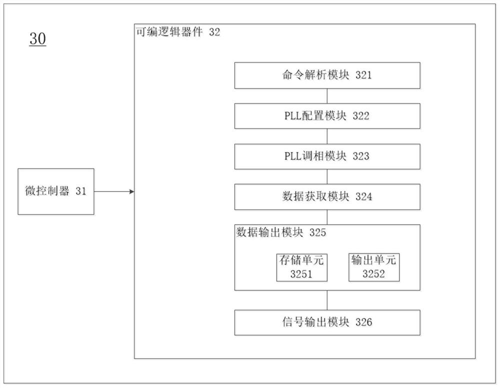
[0062] Such as image 3 As shown, the third embodiment of the present application provides a data output device. The data output device 30 includes a microcontroller 31 and a programmable logic device 32 connected to the microcontroller 31 . Wherein, the programmable logic device is used to implement the data output method as described in the first embodiment. For a specific description of the data output method, reference may be made to the first embodiment, and details are not repeated here for the sake of brevity.
[0063] Such as image 3 As shown, the programmable logic device 32 further includes: a command analysis module 321 , a PLL configuration module 322 , a PLL phase modulation module 323 , a data acquisition module 324 , a data output module 325 and a signal output module 326 .
[0064] Wherein, the command analysis module 321 is configured to receive a phase adjustment command sent by the data receiving device, and analyze the phase adjustment command to obtain...
PUM
 Abstract
Description
Claims
Application Information
 - R&D Engineer
- R&D Manager
- IP Professional
- Industry Leading Data Capabilities
- Powerful AI technology
- Patent DNA Extraction
Browse by: Latest US Patents, China's latest patents, Technical Efficacy Thesaurus, Application Domain, Technology Topic, Popular Technical Reports.
© 2024 PatSnap. All rights reserved.Legal|Privacy policy|Modern Slavery Act Transparency Statement|Sitemap|About US| Contact US: help@patsnap.com


