A raw material tank for a continuous catalytic device
A technology of catalytic device and raw material tank, which is applied in the field of raw material tank for continuous catalytic device, can solve the problem of high cost
- Summary
- Abstract
- Description
- Claims
- Application Information
AI Technical Summary
Problems solved by technology
Method used
Image
Examples
Embodiment 1
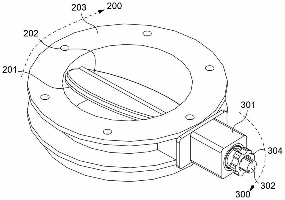
[0051] refer to Figure 1 to Figure 4 , which is the first embodiment of the present invention, which provides a raw material tank for a continuous catalytic device, which includes a storage tank 100, a valve 200 and a regulating mechanism 300, and the valve 200 is located at the outlet 101 of the storage tank 100, Valve 200 comprises valve core 201, rotating shaft 202, valve body 203, and rotating shaft 202 is located in valve body 203, and rotating shaft 202 can rotate around the axis; Valve core 201 is located in valve body 203, and valve core 201 is supported on the rotating shaft 202, and the valve core 200 The spool 201 is driven to rotate by the rotating shaft 202. Through the rotating shaft 202 rotating around the axis, the rotation of the spool 201 can be realized, so as to realize the opening or closing of the valve; wherein, the adjusting mechanism 300 is connected to the rotating shaft 202 to drive the rotating shaft 202 to rotate at a fixed angle , the rotation an...
Embodiment 2
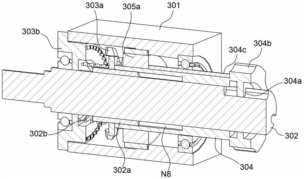
[0056] refer to Figure 2 to Figure 8 , this embodiment is different from the first embodiment in that: the second connecting piece 303b includes a supporting seat 303b-1 and a limiting tooth 303b-2, the supporting seat 303b-1 is fixedly connected with the supporting seat 301, and the supporting seat 301 is provided with an internal Cavity N6, one end of the inner cavity N6 is used for the installation of the support seat 303b-1, the support seat 303b-1 is sleeved on the outside of the connecting shaft 302 through the through hole, and a rotary bearing S1 is also provided on one side of the through hole, and the connecting shaft 302 passes through the through hole. The hole is connected with the rotating bearing S1, the connecting shaft 302 passes through the through hole, and can rotate in the through hole under the support of the rotating bearing S1; the limited teeth 303b-2 are evenly distributed on the support seat 303b along the circumference of the connecting shaft 302 -...
Embodiment 3
[0061] refer to Figure 2 to Figure 11 , this embodiment is different from the above embodiments in that: the connecting shaft 302 is provided with a guide block 302a, the guide block 302a extends in the axial direction, the operating part 304 is provided with a guide notch N7, and the operating part 304 is set through the guide notch N7 It is connected to the outside of the guide block 302a, and can guide and move along the guide block 302a through the guide notch N7;
[0062] It should be noted that the base 303a-1 is provided with a moving notch N8, the number of the moving notch N8 is the same as the number of the guide block 302a, and the base 303a-1 slides on the connecting shaft along the guide block 302a through the moving notch N8 302, the first connecting piece 303a can move relative to the second connecting piece 303b as a whole, and the first connecting piece 303a can move axially along the guide block 302a, so that the straight tooth 303a-3 can be separated from t...
PUM
 Abstract
Description
Claims
Application Information
 - Generate Ideas
- Intellectual Property
- Life Sciences
- Materials
- Tech Scout
- Unparalleled Data Quality
- Higher Quality Content
- 60% Fewer Hallucinations
Browse by: Latest US Patents, China's latest patents, Technical Efficacy Thesaurus, Application Domain, Technology Topic, Popular Technical Reports.
© 2025 PatSnap. All rights reserved.Legal|Privacy policy|Modern Slavery Act Transparency Statement|Sitemap|About US| Contact US: help@patsnap.com


