Intelligent student bed

A student and intelligent technology, applied in the field of intelligent student beds, can solve problems such as tripping, bumping, railings or railings with low heights that cannot achieve good safety effects, and achieve the effects of easy installation, fall prevention, and simple and compact structure

Pending Publication Date: 2021-05-14
JIAOZUO UNIV
View PDF4 Cites 2 Cited by
  • Summary
  • Abstract
  • Description
  • Claims
  • Application Information

AI Technical Summary

Problems solved by technology

[0003] In order to overcome the limitations of the structure of the existing student beds, there are no railings or the height of the railings is too low to achieve a good safety effect. If the railings are too high, it will affect the students getting on and off the bed, and even cause the disadvantages of tripping and bumping. , the present invention provides a student accommodation bed body, with movable railings that can be controlled to move up and down by an electric push rod. In application, under the joint action of related circuits and mechanisms, students can automatically lower the height of the movable railings before going to bed, and can The height of the movable railing is automatically restored. The movable railing has a relatively higher height, which can effectively prevent students from falling from the bed while sleeping, and the height can be automatically lowered when the student gets out of bed, which brings convenience to students and also plays a role An intelligent student bed with good safety effect

Method used


Image

  • Intelligent student bed
  • Intelligent student bed
  • Intelligent student bed

Examples


Embodiment Construction

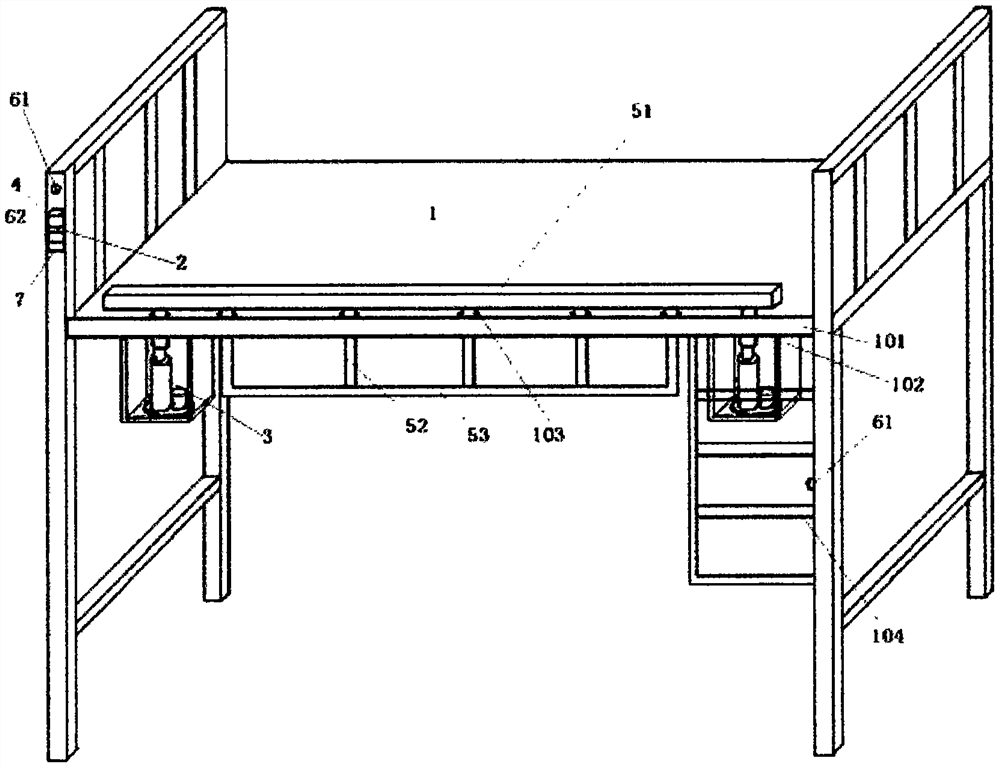
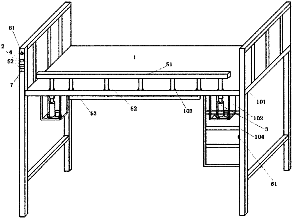
[0014] figure 1 , 2 Shown, a kind of intelligent student bed, comprises student accommodation bed body 1, stabilized voltage power supply 2, electric telescopic rod 3; Also has first control circuit, second control circuit, movable railing; The front side bed of described accommodation bed body Frame 101 is vertically welded with seven conduits 103 (the inner diameter is greater than the connecting rod outer diameter 1mm) from left to right at a certain distance. The movable railing includes upper cross bar 51, lower cross bar 52 and connecting rod 53. Seven connecting rods 53 upper ends are vertically welded on the lower end of the upper cross bar 51 at intervals of a certain distance, and seven connecting rods 53 pass through seven conduits 103 from top to bottom, wherein the lower ends of five connecting rods 53 are welded on the lower cross bar at intervals of a certain distance ( Located at the upper end of the front bed frame 101) 52; a "U"-shaped support plate 102 is r...


PUM


Abstract

The invention relates to an intelligent student bed. The intelligent student bed comprises a student accommodation bed body, a stabilized voltage supply and an electric telescopic rod; the intelligent student bed further comprises a first control circuit, a second control circuit and a movable handrail; a plurality of guide pipes are vertically mounted in front of a bed frame; the movable handrail comprises an upper cross rod, a lower cross rod and connecting rods; the upper ends of the connecting rods are mounted at the lower end of the upper cross rod; the connecting rods penetrate through the guide pipes; the lower ends of the connecting rods are mounted at the upper end of the lower cross rod; the electric push rod is installed at the upper ends of two supporting plates; the upper end of the electric push rod and the lower ends of the connecting rods at the two side ends of the upper cross rod are installed together; the first control circuit comprises two photoelectric switches and a trigger sub-circuit, wherein the first photoelectric switch is mounted at the side end of an escalator, and the second photoelectric switch is mounted on one side of the accommodation bed body; and the stabilized voltage supply, the trigger sub-circuit of the first control circuit and the second control circuit are arranged in an element box and are electrically connected with the photoelectric switches and the electric push rod. The Intelligent student bed is convenient to use; and the purpose of intelligent control can be achieved on the premise that the safety effect is fully achieved.

Description

technical field [0001] The invention relates to the technical field of student supplies and equipment, in particular to an intelligent student bed. Background technique [0002] In order to save space, existing student dormitory beds are generally divided into upper and lower layers, the upper layer is used as a student to sleep and rest, and the lower layer is provided with a writing desk for students to practice. In order not to hinder the students going to bed, the existing student dormitory beds generally do not have a railing at the front end of the upper bed or the height of the railing is very low. big security risk. Specifically, when students accidentally turn over too much while sleeping, they may fall from the bed to the ground (the fence is too low to achieve a good blocking effect), which will cause unpredictable and serious consequences. Although heightening the railings can solve the problem of students sleeping on the ground, excessively high railings will ...

Claims


Application Information

Patent Timeline
Patent Type & Authority Applications(China)
IPC IPC(8): A47C19/22A47C19/02A47C17/86
CPCA47C19/22A47C19/02A47C17/86
Inventor 邢文生周军陈巧云
Owner JIAOZUO UNIV
Why Eureka
Try Eureka