
Quick mounting device for wet joint suspended formwork bottom plate

An installation device and wet seam technology, which is applied in the field of quick installation devices for wet seam hanging formwork bottom plates, can solve the problems of high height, low efficiency, inconvenient movement, etc., and achieve the effects of flexible setting, convenient use and simple device structure

Pending Publication Date: 2021-05-07
RAILWAY NO 10 ENG GRP CO LTD +1
View PDF0 Cites 1 Cited by
  • Summary
  • Abstract
  • Description
  • Claims
  • Application Information

AI Technical Summary

Problems solved by technology

If a mobile formwork is installed at the bottom of the beam, it is very inconvenient to move in actual operation. Most of the formwork at the bottom of the beam cannot be moved, and the height required is often large, and the height is too large will greatly increase the unsafe factor, and The lifting operation is carried out at the bottom of the beam, and the overall efficiency is too low
There are also existing mobile platforms on it, but most of them are manually operated, and during the operation, since the upper and lower wet joints cannot be directly observed, it is impossible to visually observe whether the hoisted formwork is hoisted in place. It is often observed by the naked eye of the personnel at the bottom, and most of the bottom of the seam has redundant seams, so it is not easy to carry out accurate monitoring. Therefore, in order to solve the above problems, relying on the actual needs of the project, it is necessary to design and manufacture a wet seam quick lifting mold device

Method used


Image

  • Quick mounting device for wet joint suspended formwork bottom plate

Examples


Embodiment Construction

[0012] The following will clearly and completely describe the technical solutions in the embodiments of the present invention with reference to the accompanying drawings in the embodiments of the present invention. Obviously, the described embodiments are only some, not all, embodiments of the present invention. Based on the embodiments of the present invention, all other embodiments obtained by persons of ordinary skill in the art without making creative efforts belong to the protection scope of the present invention.

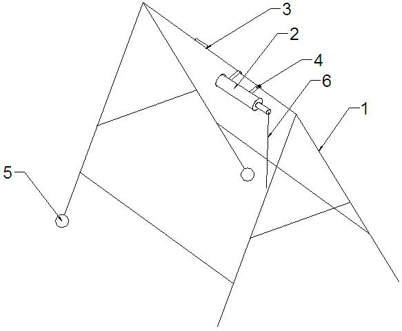
[0013] like figure 1 As shown, the present invention includes a support frame 1, a stay rope 6 and an electric hoist 2, the section of the support frame 1 is an A-shaped structure, the electric hoist 2 is fixedly arranged on the top of the support frame 1, and the bottom of the support frame 1 A roller 5 is provided, and one end of the stay rope 6 is fixedly connected with the output shaft of the electric hoist 2, and the other end is provided with a hook for ...


PUM


Abstract

The invention discloses a quick mounting device for a wet joint suspended formwork bottom plate, which comprises a supporting frame, a pull rope and an electric hoist, the cross section of the supporting frame is of an A-shaped structure, an electric pulley is fixedly arranged at the top of the supporting frame, rollers are arranged at the bottom of the supporting frame, one end of the pull rope is fixedly connected with an output shaft of the electric hoist, and the other end of the pull rope is fixedly connected with the output shaft of the electric hoist. And a hook is arranged at the other end and is used for being hung on a mold hanging bottom plate. The electric hoist is arranged at the bottom of the A-shaped supporting frame, and the end of the electric hoist is hung on the hanging mold bottom plate through the pull rope, so that lifting of the hanging mold can be achieved by operating the electric hoist in a labor-saving mode, and the purposes of saving energy, reducing consumption and improving quality and efficiency are achieved; furthermore, through vertically arranging a distance measuring instrument on the supporting frame, the distance between the hoisting bottom plate and the supporting frame is measured, then the height of the hoisting bottom plate can be visually observed in real time, and the damage that the hoisting height is not in place or after the hoisting height is in place, an electric hoist continues to hoist to burn a motor is avoided.

Description

technical field [0001] The invention relates to the technical field of building construction, in particular to a quick installation device for a wet joint suspension formwork bottom plate. Background technique [0002] At present, after the T-beams are erected, it is necessary to mold the wet joints between the T-beams, but the space of the wet joints is too small (only 50cm wide) and suspended, and there is no platform for workers to install molds. If a mobile formwork is installed at the bottom of the beam, it is very inconvenient to move in actual operation. Most of the formwork at the bottom of the beam cannot be moved, and the height required is often large, and the excessive height will greatly increase the unsafe factor, and The lifting operation is carried out at the bottom of the beam, and the overall efficiency is too low. There are also existing mobile platforms on it, but most of them are manually operated, and during the operation, since the upper and lower wet...

Claims


Application Information

Patent Timeline
Patent Type & Authority Applications(China)
IPC IPC(8): E01D21/00E04G13/00E04G17/00
CPCE01D21/00E04G13/00E04G17/00
Inventor 何玉文曾云旭王利军焦柏源郅雨淼魏德忠张杰李方华李凯凯贾彬安建华
Owner RAILWAY NO 10 ENG GRP CO LTD
Learn More