
Liftable transverse beam for bridge crane and operation method

A technology of bridge cranes and lifting beams, applied in the directions of lifting equipment braking devices, load hanging elements, bottom support structures, etc., can solve problems such as bending, beam tilting, and easy toppling of devices

Pending Publication Date: 2021-04-30
武汉永铖机械工程有限公司
View PDF1 Cites 0 Cited by
  • Summary
  • Abstract
  • Description
  • Claims
  • Application Information

AI Technical Summary

Problems solved by technology

[0003] After retrieval, the Chinese patent application number is 201920413172.X, and the patent publication number is CN210048392U, which discloses a liftable beam for bridge cranes. The above-mentioned device can not only realize the parallel lateral movement of the beam, but also combine the liftable mechanism to realize the beam It can be adjusted up and down to adapt to the lifting and hoisting of different goods, which greatly improves the practicability, effectively realizes the lifting of the beam, facilitates the operation of the bridge crane, and effectively realizes the lifting needs of various goods. However, the above-mentioned device is in use In the process, there is a disadvantage of low stability, and the whole device is easy to topple over. At the same time, when the beam of the above device is raised and lowered, there is no fixing mechanism. As a result, after the beam is raised, the weight of the beam as a whole acts on the two lifting support rods. The stability is not high, it is easy to cause the beam to tilt or even bend the lifting support rod

Method used


Image

  • Liftable transverse beam for bridge crane and operation method
  • Liftable transverse beam for bridge crane and operation method
  • Liftable transverse beam for bridge crane and operation method

Examples


Embodiment Construction

[0024] The following will clearly and completely describe the technical solutions in the embodiments of the present invention with reference to the accompanying drawings in the embodiments of the present invention. Obviously, the described embodiments are only some, not all, embodiments of the present invention.

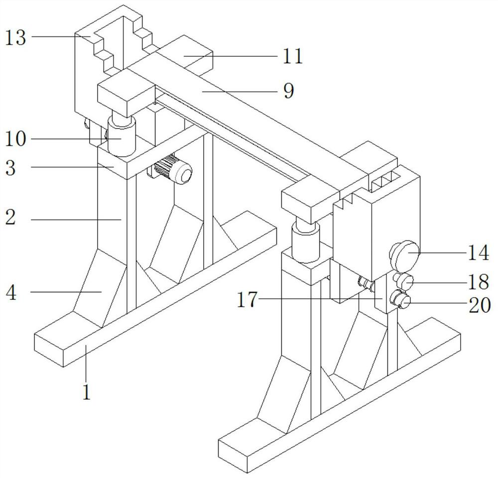
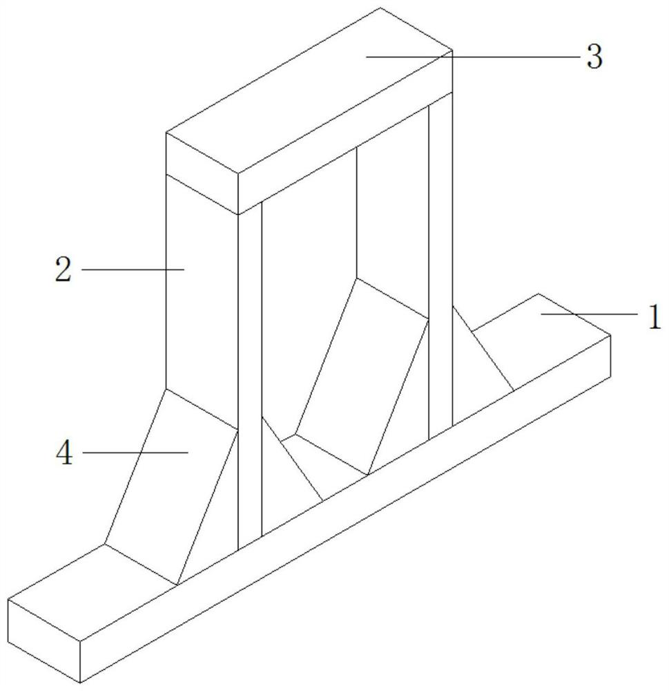
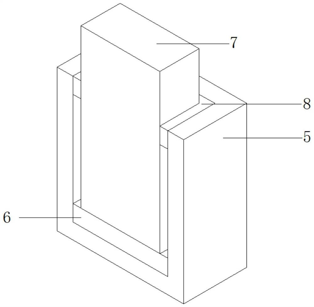
[0025] refer to Figure 1-5 , a liftable beam for a bridge crane, comprising two base plates 1, a support mechanism is provided on the top outer walls of the two base plates 1, and the support mechanism includes two support plates 2, and the two support plates 2 Welded on the outer walls at both ends of the top of the bottom plate 1 respectively, a horizontal plate 3 is arranged above the bottom plate 1, and the two ends of the horizontal plate 3 are respectively welded on the top outer walls of the two support plates 2, and the top outer walls of the two horizontal plates 3 All are equipped with a lifting mechanism, the lifting mechanism includes a support frame 5, ...


PUM


Abstract

The invention discloses a liftable transverse beam for a bridge crane and an operation method. The liftable transverse beam comprises two bottom plates, wherein supporting mechanisms are arranged on the outer walls of the tops of the two bottom plates. Each supporting mechanism comprises two supporting plates, wherein the two supporting plates of each supporting mechanism are welded to the outer walls of the two ends of the top of the corresponding bottom plate, a transverse plate is arranged above each bottom plate, the two ends of each transverse plate are welded to the outer walls of the tops of the two corresponding supporting plates, and lifting mechanisms are arranged on the outer walls of the tops of the two transverse plates correspondingly. Each lifting mechanism comprises a supporting frame, wherein the bottom of each supporting frame is welded to the outer wall of the top of the corresponding transverse plate, a sliding plate is installed in each supporting frame in a sliding mode, a supporting column is welded to the outer wall of the top of each sliding plate, and a limiting frame is welded to the inner wall of the top end of each supporting frame. According to the liftable transverse beam for the bridge crane and the operation method, the stability is improved, the overall supporting strength of a device is improved, the height of a guide rail can be adjusted, the bridge crane can be suitable for hoisting occasions with different heights, the flexibility is improved, fixing blocks and the guide rail can be supported, the guide rail is prevented from being inclined, and the safety is improved.

Description

technical field [0001] The invention relates to the technical field of bridge cranes, in particular to a liftable crossbeam for bridge cranes and an operation method. Background technique [0002] The bridge crane is a lifting device that is horizontally placed over the workshop, warehouse and stockyard for material lifting. Because its two ends are located on tall cement columns or metal supports, it is shaped like a bridge. The bridge frame of the bridge crane runs longitudinally along the tracks laid on the elevated sides on both sides, which can make full use of the space under the bridge frame to lift materials without being hindered by ground equipment. It is a kind of hoisting machinery with the widest range and the largest number. [0003] After retrieval, the Chinese patent application number is 201920413172.X, and the patent publication number is CN210048392U, which discloses a liftable beam for bridge cranes. The above-mentioned device can not only realize the pa...

Claims


Application Information

Patent Timeline
IPC IPC(8): B66C5/04
CPCB66C5/04
Inventor 黄斌润黄润霞
Owner 武汉永铖机械工程有限公司
Learn More