
Camera components and electronics

A technology of camera components and camera modules, which is applied in the electronic field and can solve problems such as loud noise of camera modules

Active Publication Date: 2022-05-10
VIVO MOBILE COMM CO LTD
View PDF6 Cites 0 Cited by
  • Summary
  • Abstract
  • Description
  • Claims
  • Application Information

AI Technical Summary

Problems solved by technology

[0002] With the development of electronic technology, people have higher and higher requirements for taking pictures of electronic equipment. Therefore, many cameras with specific functions are installed on electronic equipment. During the process of implementing this application, the applicant found that there are at least the following Problem: Due to the needs of the shooting effect, the camera module is set to move relative to the bracket, but when the camera module on the electronic device can move relative to the bracket, shaking the electronic device will make the noise of the camera module louder

Method used


Image

  • Camera components and electronics
  • Camera components and electronics
  • Camera components and electronics

Examples


Embodiment Construction

[0018] Embodiments of the present application will be described in detail below, examples of which are shown in the drawings, in which the same or similar reference numerals denote the same or similar elements or elements having the same or similar functions throughout. The embodiments described below by referring to the figures are exemplary, and are only for explaining the present application, and should not be construed as limiting the present application. Based on the embodiments in this application, all other embodiments obtained by persons of ordinary skill in the art without creative efforts fall within the protection scope of this application.

[0019] The features of the terms "first" and "second" in the description and claims of the present application may explicitly or implicitly include one or more of these features. In the description of the present application, unless otherwise specified, "plurality" means two or more. In addition, "and / or" in the specification ...


PUM


Abstract

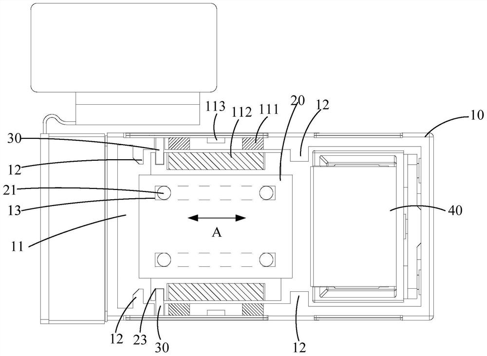
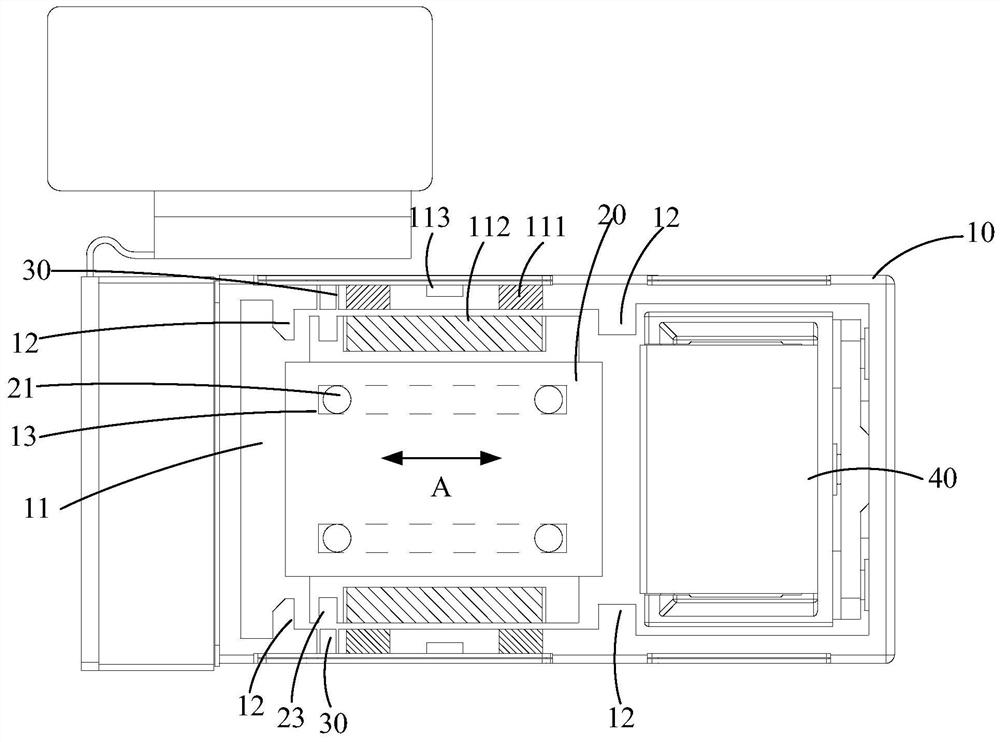
The present application discloses a camera assembly and an electronic device. The camera assembly includes: a bracket, a camera module, and a limiting member. The bracket includes an accommodation cavity, and the camera module and the limiting member are both accommodated in the The accommodating cavity, and the limiting member is arranged on the camera module or the inner wall of the accommodating cavity. In this way, when the camera module is in the first state, the limiting member abuts against the inner wall of the accommodating cavity or the camera module, thereby forming a limiting effect on the camera module, reducing the movement of the camera module relative to the bracket, and The appearance of noise caused by collision with other parts.

Description

technical field [0001] The present application belongs to the field of electronic technology, and in particular relates to a camera assembly and electronic equipment. Background technique [0002] With the development of electronic technology, people have higher and higher requirements for taking pictures of electronic equipment. Therefore, many cameras with specific functions are installed on electronic equipment. During the process of implementing this application, the applicant found that there are at least the following Problem: Due to the needs of the shooting effect, the camera module is set to move relative to the bracket, but when the camera module on the electronic device can move relative to the bracket, shaking the electronic device will make the noise of the camera module louder. Contents of the invention [0003] The purpose of the present application is to provide a camera assembly and electronic equipment, at least to solve the problem of relatively large no...

Claims


Application Information

Patent Timeline
Patent Type & Authority Patents(China)
IPC IPC(8): H04N5/225H04M1/02
CPCH04M1/0264H04N23/50
Inventor 支援
Owner VIVO MOBILE COMM CO LTD
Learn More