
Water treatment equipment

A water treatment equipment and water pump technology, applied in water/sewage treatment, thermal storage equipment, water/sludge/sewage treatment, etc., can solve the problems of not being able to produce cold water immediately, being large in size, and prone to failures.

Inactive Publication Date: 2021-04-09
GUANGDONG MIDEA WHITE HOME APPLIANCE TECH INNOVATION CENT CO LTD +1
View PDF9 Cites 1 Cited by
  • Summary
  • Abstract
  • Description
  • Claims
  • Application Information

AI Technical Summary

Problems solved by technology

[0002] At present, water treatment equipment uses compressors or semiconductor refrigeration modules to cool water. Freon is used for compressor refrigeration. This method is not conducive to environmental protection, and the compressor is noisy and energy-consuming.
For semiconductor refrigeration, the amount of cold water discharged at a time is small, the effect is poor, and failures are prone to occur.
In order to ensure that users can use cold water in a timely manner, whether it is semiconductor refrigeration or compressor refrigeration, because the water production speed of the two is slow and cannot immediately produce cold water, it is necessary to set up a water tank to store cold water, and the setting of the water tank makes the equipment Overall volume is large

Method used


Image

  • Water treatment equipment
  • Water treatment equipment
  • Water treatment equipment

Examples


example 1

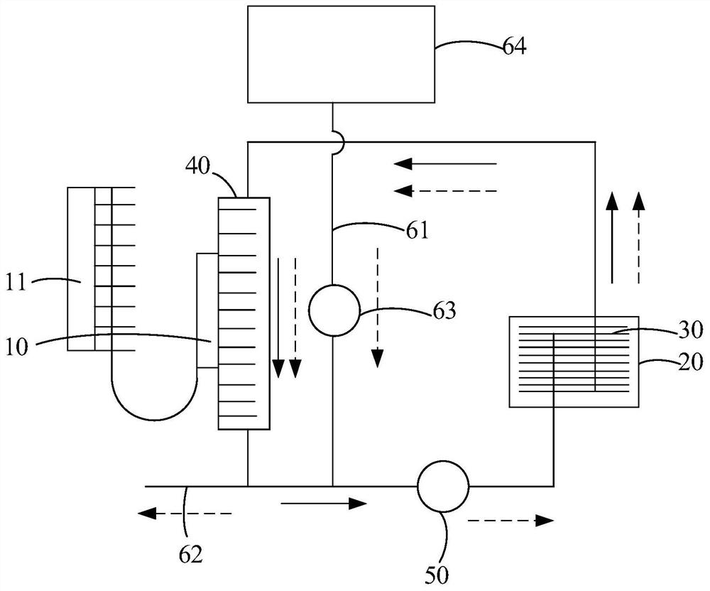
[0057] The cold water temperature in the energy storage loop is 3.1°C (referring to the energy storage loop when the water inlet solenoid valve 63 is closed), the inlet water temperature of the water inlet pipe 61 is 25°C, and the phase change heat exchanger 30 is a plate heat exchanger device, the heat exchange area of ​​the phase change heat exchanger 30 is 0.17m 2 , the phase change temperature of the phase change material is 5°C, and the thermal conductivity is 0.2W / m.K. At this time, take 1L of water continuously, and the final water temperature in the cup is about 12.8°C; take another 250ml of water at an interval of 5 minutes, and you can get 3 cups of water below 10°C.

example 2

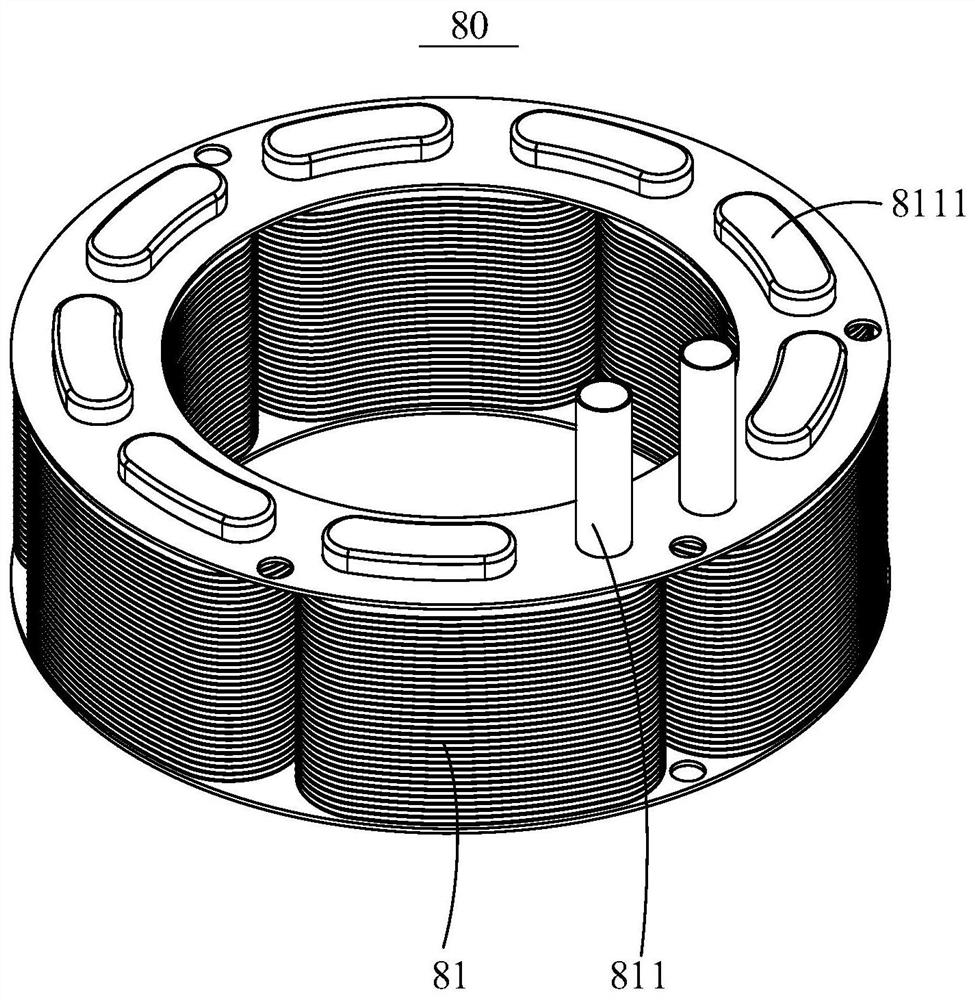
[0059] The cold water temperature in the energy storage loop is 3.1°C (referring to the energy storage loop when the water inlet solenoid valve 63 is closed), the inlet water temperature of the water inlet pipe 61 is 25°C, and the phase change heat exchanger 30 is a finned tube type Heat exchanger 80, the heat exchange area of ​​phase change heat exchanger 30 is 0.17m 2 , the phase change temperature of the phase change material is 5°C, and the thermal conductivity is 0.6W / m.K. At this time, take 1L of water continuously, and the final water temperature in the cup is about 9.6°C; take another 250ml of water at an interval of 5 minutes, and you can get 5 cups of water below 10°C.

example 3

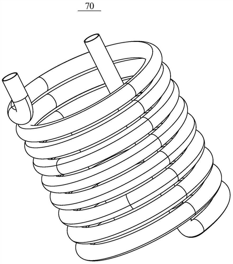
[0061] The cold water temperature in the energy storage loop is 3.1°C (referring to the energy storage loop when the water inlet solenoid valve 63 is closed), the inlet water temperature of the water inlet pipe 61 is 25°C, and the phase change heat exchanger 30 is a bare tube type Heat exchanger 70, the heat exchange area of ​​phase change heat exchanger 30 is 0.078m 2 , the phase change temperature of the phase change material is 5°C, and the thermal conductivity is 1W / m.K. At this time, take 1L of water continuously, and the final water temperature in the cup is about 12.5°C; take another 250ml of water at an interval of 5 minutes, and you can get 3 cups of water below 10°C.


PUM

PropertyMeasurementUnit
Phase transition temperatureaaaaaaaaaa
Thermal conductivityaaaaaaaaaa
Heat transfer areaaaaaaaaaaa

Abstract

The invention discloses water treatment equipment, which comprises an energy storage box, an energy storage loop, a heat exchange module, a water inlet pipe and a water outlet pipe, wherein a phase change material is arranged in the energy storage box; the energy storage loop comprises a phase change heat exchanger, an energy taking heat exchanger and a water pump which sequentially communicate, and the phase change heat exchanger is located in the energy storage box; the heat exchange module is used for refrigerating or heating the energy taking heat exchanger; the water inlet pipe is connected with the energy storage loop; and the water outlet pipe is connected with the energy storage loop. According to the technical scheme, the water treatment equipment can achieve rapid water refrigeration / heating.

Description

technical field [0001] The invention relates to the technical field of household appliances, in particular to water treatment equipment. Background technique [0002] At present, water treatment equipment realizes cooling water through compressors or semiconductor refrigeration modules, and Freon is used for refrigeration of compressors. This method is not conducive to environmental protection, and the operation noise of compressors is large, and energy consumption is high. For semiconductor refrigeration, the amount of cold water discharged at a time is small, the effect is poor, and failures are prone to occur. In order to ensure that users can use cold water in a timely manner, whether it is semiconductor refrigeration or compressor refrigeration, because the water production speed of the two is slow and cannot immediately produce cold water, it is necessary to set up a water tank to store cold water, and the setting of the water tank makes the equipment The overall volu...

Claims


Application Information

Patent Timeline
IPC IPC(8): F25D31/00F28D20/00C02F1/00
CPCF25D31/002F28D20/00C02F1/00Y02E60/14
Inventor 何凤英熊玉明陈龙
Owner GUANGDONG MIDEA WHITE HOME APPLIANCE TECH INNOVATION CENT CO LTD
Learn More