
A glass handling device

A handling device and glass technology, applied in the direction of transportation and packaging, furnace, electric charge control, etc., can solve the problems of affecting work efficiency, not stable enough, glass breakage, etc., and achieve the effect of convenient operation, stable transportation, and reduction of glass breakage

Active Publication Date: 2022-04-01
ZHEJIANG JINGTAI GLASS TECH +1
View PDF4 Cites 0 Cited by
  • Summary
  • Abstract
  • Description
  • Claims
  • Application Information

AI Technical Summary

Problems solved by technology

[0003] During the production and processing of glass, it needs to be transported many times. Nowadays, during the manufacturing and processing, the glass is usually lifted by the aircraft for transportation. However, when the aircraft is transported, there are some paths that cannot be connected by the aircraft. Currently, manual handling is usually used. Or use a cart to transport, but this method is time-consuming and laborious, affects work efficiency, is not stable enough, and often causes glass to break

Method used


Image

  • A glass handling device
  • A glass handling device
  • A glass handling device

Examples


Embodiment 1

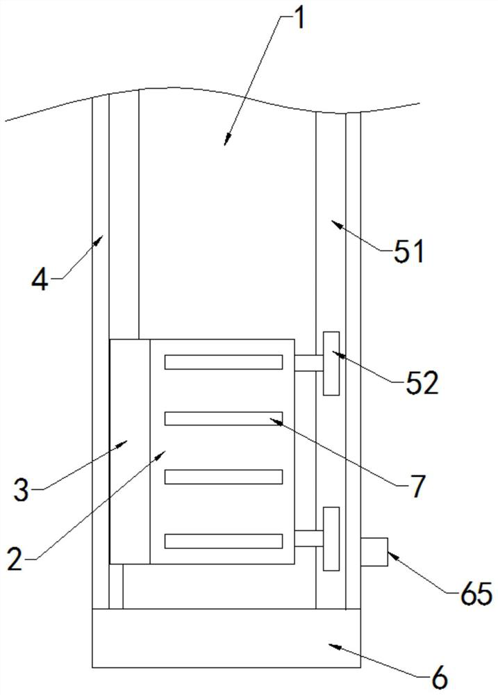
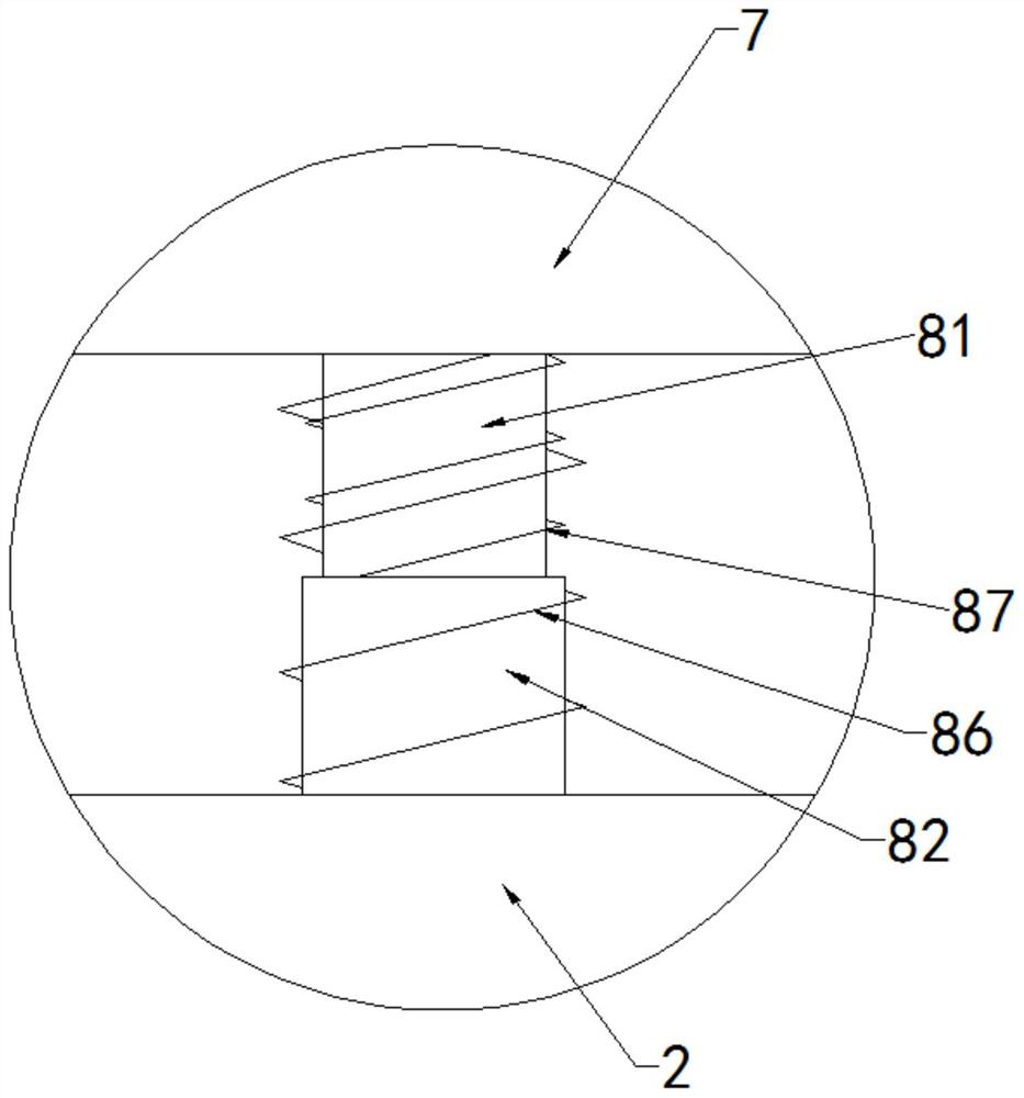
[0031] like Figure 1 to Figure 6As shown, the present invention discloses a glass handling device. In a specific embodiment of the present invention, it includes a base 1 fixed on the ground, and the base 1 is provided with a conveying mechanism that can move on the base 1 . The conveying mechanism includes a carrier plate 2 for carrying glass and a backing plate 3 vertically arranged on one side of the carrier plate 2, a limiting plate 4 is fixed on the side of the backing plate 3 away from the carrier plate 2 on the base 1, the The limit block 41 is fixed on the back plate 3, and the limit plate 4 is provided with a limit chute 42 for the limit block 41 to slide therein. The limit chute 42 is a T-shaped groove to prevent the limit Block 41 escapes from the limit chute 42, and the backing plate 3 is connected with the limit plate 4 through the limit block 41, and the end of the back plate 3 away from the limit plate 4 is fixed with a sponge protective layer 31; The board 2 ...

Embodiment 2

[0042] like Figure 7 and Figure 8 As shown, the difference between this embodiment and the above-mentioned embodiments is that: in this embodiment, the backing plate 3 is also provided with an adsorption mechanism, and the adsorption mechanism includes a Several suction cups 9 and the suction fan 11 and the suction pipe 10 installed on the back plate 3 away from the end of the suction cup 9, the suction cups 9 are evenly arranged on the back plate 3, and the back plate 3 is correspondingly provided with each suction cup 9 The air suction port 12 communicated, the air suction pipe 10 communicates with the air suction fan 11 , and the air suction pipe 10 communicates with the air suction port 12 .

[0043] In this embodiment, the suction cup 9 includes a connecting base 91, an inner disc body 92 and an outer disc body 93, the connecting base 91 is fixed on the backing plate 3, the outer disc body 93 is fixed on the connecting base 91, the inner disc The body 92 is fixed at t...


PUM


Abstract

The technical solution of the present invention is achieved as follows: a glass handling device, characterized in that it includes a base fixed on the ground, and a conveying mechanism that can move on the base is provided on the base, and the conveying mechanism includes a The bearing plate that carries the glass and the backing plate vertically arranged on one side of the loading plate, the limiting plate is fixed on the side of the backing plate away from the loading plate on the base, the limiting block is fixed on the backing plate, and the limiting A limit chute for the limit block to slide is opened on the plate, and the support plate is connected with the limit plate through the limit block; the bearing plate is arranged on the base through a transmission mechanism, and the transmission mechanism includes a fixed The track on the base, the rollers arranged on the track and the driving motor that controls the rotation of the rollers, a connecting rod is arranged between the two rollers, and the rollers and the tracks are provided with mutually cooperating teeth; the beneficial effects of the present invention are: It is convenient and stable to transport glass, and the glass is not easy to break.

Description

technical field [0001] The invention relates to the technical field of glass conveying equipment, in particular to a glass conveying device. Background technique [0002] Glass is an amorphous inorganic non-metallic material. It is generally made of a variety of inorganic minerals as the main raw material and a small amount of auxiliary raw materials. Its main components are silicon dioxide and other oxides; the chemical composition of ordinary glass is Na2SiO3, CaSiO3 , SiO2 or Na2O CaO 6SiO2, etc., the main component is silicate double salt, which is an amorphous solid with an irregular structure; it is widely used in buildings, used to separate wind and light, and belongs to the mixture. In recent years, glass The heat is loved by people, and the demand for glass has increased significantly. [0003] During the production and processing of glass, it needs to be transported many times. Nowadays, during the manufacturing and processing, the glass is usually lifted by the a...

Claims


Application Information

Patent Timeline
Patent Type & Authority Patents(China)
IPC IPC(8): B65G49/06
CPCB65G49/061B65G49/064
Inventor 王建晓叶志斌邓小雷
Owner ZHEJIANG JINGTAI GLASS TECH
Learn More