
Cutting machine with intelligent lifting tail frame

A technology of cutting machine and tailstock, which is applied in the field of cutting machines with intelligent lifting tailstock, which can solve problems such as diagonal imbalance of the frame body, deviation of material properties, and impact on cutting quality, and achieve the effect of avoiding diagonal imbalance

Pending Publication Date: 2021-04-09
ZHEJIANG JIATAI LASER SCI & TECH CO LTD
View PDF16 Cites 0 Cited by
  • Summary
  • Abstract
  • Description
  • Claims
  • Application Information

AI Technical Summary

Problems solved by technology

[0003] In the process of laser cutting, there will be extremely high requirements for the flatness of the material placement. If the material is uneven, it will lead to a problem of great deviation in the properties of the material after cutting, which will greatly affect the laser cutting process. Therefore, in the prior art, the tailstock is used to place materials to provide to the upper cutting head for cutting. In order to ensure the flatness of the existing tailstock structure, cylinders are set at the four corners of the frame. During the cutting process, the entire frame is lifted by the cylinder to ensure the flatness during the cutting process. However, during the operation of the cylinder, there will be air supply speed and gaps that make the push rods of the four cylinders rise. There are some deviations from the angle and the angle, which will cause the whole frame to be unbalanced diagonally, which seriously affects the cutting quality

Method used


Image

  • Cutting machine with intelligent lifting tail frame
  • Cutting machine with intelligent lifting tail frame
  • Cutting machine with intelligent lifting tail frame

Examples


Embodiment Construction

[0018] The present invention will be further described in detail below with reference to the embodiments given in the accompanying drawings.

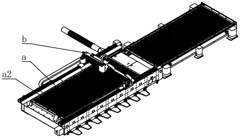
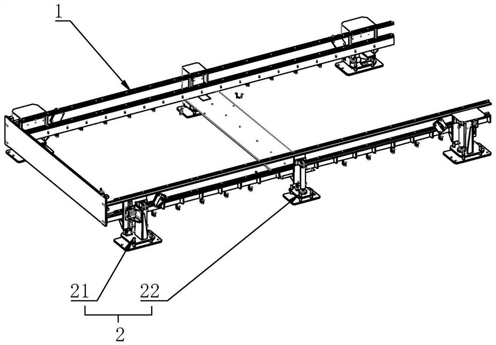
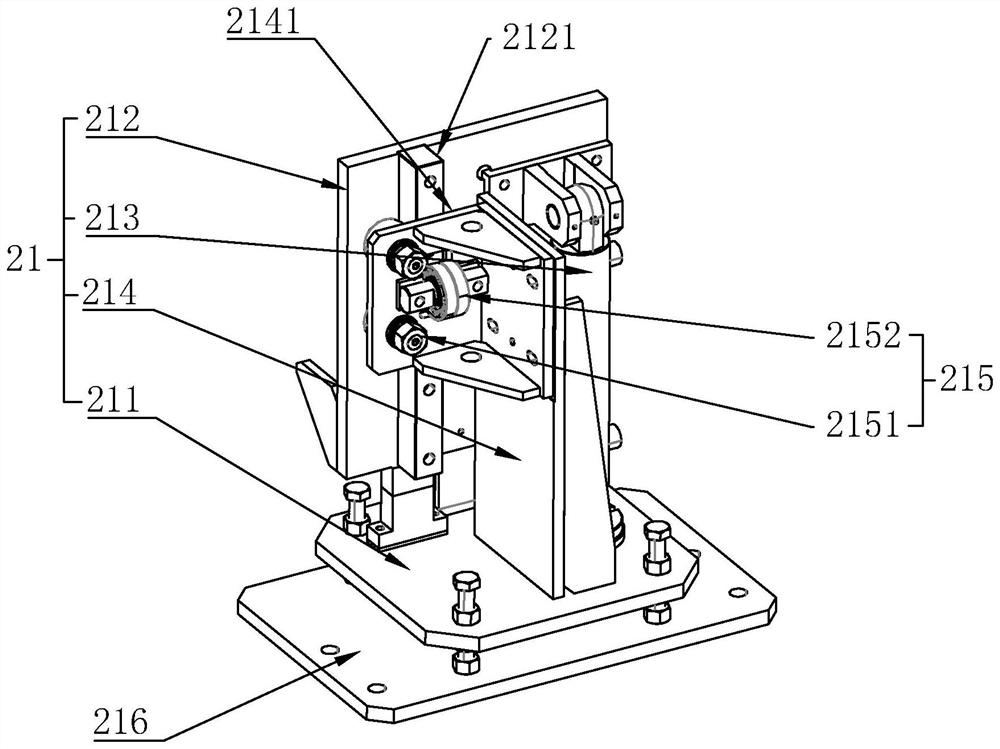
[0019] refer to Figures 1 to 5 As shown, a cutting machine with an intelligent lifting tailstock in this embodiment includes a cutting frame a and a slidable laser head b arranged on the cutting frame a, and the cutting frame a includes a tailstock and is installed on The cutting platform in the tailstock, slide rails are fixedly installed on the upper sides of the left and right sides of the tailstock, the laser head b includes a head and a slide bar, and the head is slidably mounted on the slide bar. Both ends of the slide bar can be slidably arranged on the slide rails, the tailstock includes a frame body 1 and a lifting device 2 arranged on the lower side of the frame body 1, and the lifting device 2 includes a corner lifting assembly 21 and a middle part Lifting assembly 22, the corner lifting assembly 21 is installed on the four...


PUM


Abstract

The invention discloses a cutting machine with an intelligent lifting tail frame. The cutting machine comprises a cutting frame and a laser head arranged on the cutting frame in a sliding mode. The cutting frame comprises the tail frame and a cutting platform installed in the tail frame, sliding rails are fixedly installed on the upper side faces of the left side and the right side of the tail frame, and the laser head comprises a head and a sliding rod. The head is slidably mounted on the sliding rod, the two ends of the sliding rod are slidably arranged on the sliding rails, a lifting device comprises corner lifting assemblies and a middle lifting assembly, the corner lifting assemblies are mounted at the four corners of the frame body, and the middle lifting assembly is mounted in the middle of the frame body. According to the cutting machine with the intelligent lifting tail frame, the lifting device comprises the corner lifting assemblies and the middle lifting assembly, the four corners and the middle of the frame body can be effectively jacked up in the jacking process, and therefore the problem of unbalanced opposite corners is avoided.

Description

technical field [0001] The invention relates to a laser cutting device, more specifically to a cutting machine with an intelligent lifting tailstock. Background technique [0002] Laser cutting is currently a more commonly used cutting method. It has the advantages of small cutting marks, good cutting controllability, etc., and the cutting edge after cutting generally does not have burrs. Therefore, laser cutting is widely used in the process of processing various materials. extensive. [0003] In the process of laser cutting, there will be extremely high requirements for the flatness of the material placement. If the material is uneven, it will lead to a problem of great deviation in the properties of the material after cutting, which will greatly affect the laser. Therefore, in the prior art, the tailstock is used to place materials to provide to the upper cutting head for cutting. In order to ensure the flatness of the existing tailstock structure, cylinders are set at t...

Claims


Application Information

Patent Timeline
Patent Type & Authority Applications(China)
IPC IPC(8): B23K26/38B23K26/70
CPCB23K26/38B23K26/702
Inventor 陈浩郑长和陈大建
Owner ZHEJIANG JIATAI LASER SCI & TECH CO LTD
Learn More