Manufacturing equipment for reinforcement cage framework
A technology for manufacturing equipment and steel cages, applied in the field of manufacturing equipment for steel cage skeletons, can solve the problem of not being able to automatically process steel cages, etc., and achieve the effect of improving the scope of use, guaranteeing welding speed, and guaranteeing welding quality.
- Summary
- Abstract
- Description
- Claims
- Application Information
AI Technical Summary
Problems solved by technology
Method used
Image

Examples
Embodiment 1
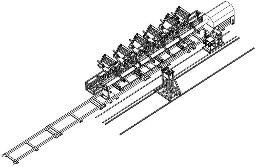
[0063] Such as Figure 1~3 As shown, the manufacturing equipment for the steel cage skeleton includes a central rotating assembly, an inner ring fixing assembly, and the inner ring fixing assembly is arranged on the central rotating assembly, and also includes a main reinforcement welding head, and the main reinforcement welding head includes an inner Ring position detection mechanism 9, welding torch chuck 6, main rib fixing device A, the inner ring position detection mechanism 9 is movably arranged on the machine head body along the left and right direction and can touch the inner ring, the inner ring position detection The mechanism 9 determines the position of the welding spot between the inner ring and the main rib by touching the inner ring; the welding torch chuck 6 cooperates with the inner ring position detection mechanism 9 and is movably arranged on the machine head body in the left and right direction Above, the welding torch chuck 6 is used to install the welding ...
Embodiment 2
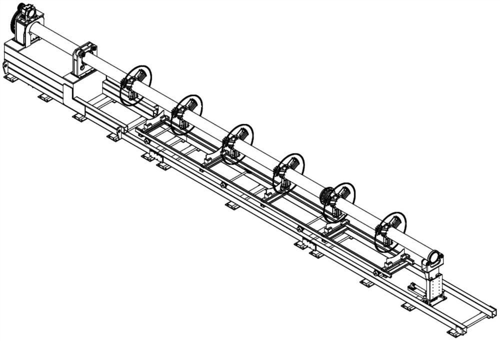
[0067] Such as Figure 4-7 As shown, this embodiment is further limited on the basis of Embodiment 1. The central rotating assembly includes a central base 1701, a fixed support end 1702 arranged on the central base 1701, a driving end 1703, and a fixed The central shaft 1704 of the support end 1702, and one end of the central shaft 1704 is connected to the driving end 1703 in transmission, and also includes a lifting support end 1705 arranged at the other end of the central shaft 1704, and the fixed support end 1702 and the lifting support end 1705 are all connected to the center The shaft 1704 is rotatably connected, the fixed support end 1702 is located between the driving end 1703 and the lifting support end 1705, and the driving end 1703 is used to drive the central shaft 1704 to rotate around its own center line.
[0068] Further, the driving end 1703 includes a driving base, a rotary motor arranged on the driving base, and the central shaft 1704 is connected to the outp...
Embodiment 3
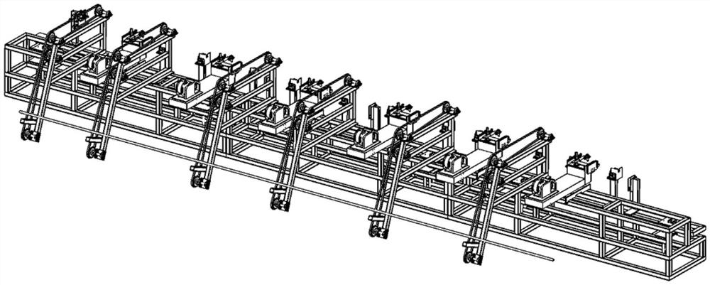
[0073] Such as Figures 8 to 13 , this embodiment is further limited on the basis of Embodiment 1, the detection mechanism includes a lifting assembly connected to the base 1, and also includes a clamping assembly arranged on the lifting assembly, several roller support assemblies, several A stopper 2, the clamping assembly is used to clamp the main rib, and the clamping assembly drives the main rib to move linearly towards the stopper 2.
[0074] In this embodiment, the base 1 is made of steel structure, the side of the base 1 is "L" shape, the lifting assembly is located on the horizontal end of L, and the clamping assembly and stopper 2 are respectively located at both ends of the lifting assembly; in this embodiment , the clamping assembly and the stopper 2 are mounted on the lifting assembly in a detachable manner, the detachable method may be a threaded connection, which is convenient for adjusting the position of the stopper 2 relative to the clamping assembly, and can ...
PUM
 Abstract
Description
Claims
Application Information
 - R&D
- Intellectual Property
- Life Sciences
- Materials
- Tech Scout
- Unparalleled Data Quality
- Higher Quality Content
- 60% Fewer Hallucinations
Browse by: Latest US Patents, China's latest patents, Technical Efficacy Thesaurus, Application Domain, Technology Topic, Popular Technical Reports.
© 2025 PatSnap. All rights reserved.Legal|Privacy policy|Modern Slavery Act Transparency Statement|Sitemap|About US| Contact US: help@patsnap.com