Production process of plastic cylindrical medicine storage tank
The invention relates to a production process and a technology for a medicine storage tank, which is applied to the production technology field of a plastic cylindrical medicine storage tank, and can solve the problems such as the decline in the molding quality of the bottle body, the difficult positioning of the cylinder body and the cover, and the inaccurate positioning of the cover and the cylinder. To achieve the effect of convenient operation, firm fixation and accurate positioning
- Summary
- Abstract
- Description
- Claims
- Application Information
AI Technical Summary
Problems solved by technology
Method used
Image
Examples
Embodiment 1
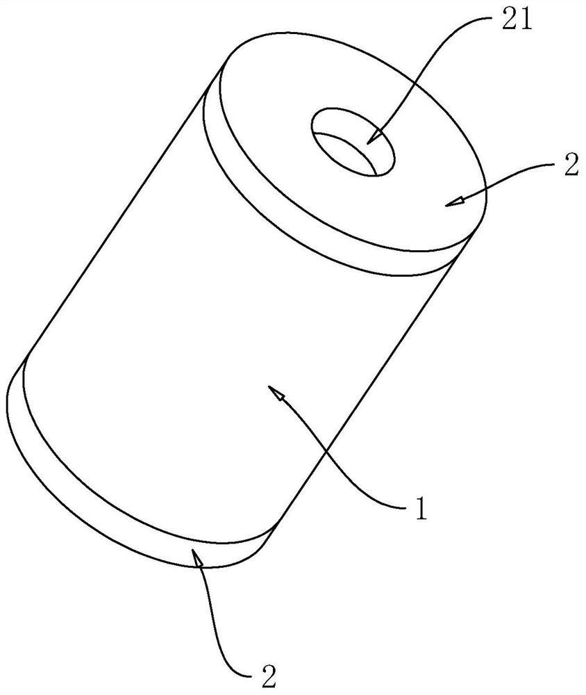
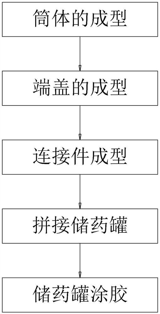
[0055] Embodiment one: refer to figure 2 and image 3, a production process of a plastic cylindrical drug storage tank adopts the following technical scheme:
[0056] S1, forming of barrel 1:
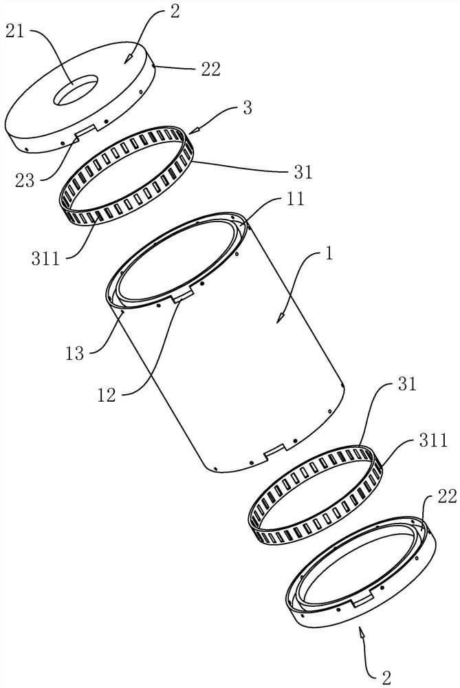
[0057] 1. Form the cylinder 1 according to the size of the cylinder 1 to be processed;
[0058] 2. Form ring grooves 11 with the same diameter as the cylinder body 1 on both ends of the cylinder body 1;
[0059] 3. Open a glue injection port 12 connected to the ring groove 11 at the end of the cylinder 1;
[0060] 4. Open a plurality of through holes 13 connected to the ring groove 11 at the end of the outer peripheral surface of the cylinder body 1, and the plurality of through holes 13 are uniformly arranged around the axis of the cylinder body 1;
[0061] 5. A bevel 1 is provided on the outer peripheral surface of the end of the cylinder body 1;
[0062] S2: Forming of end cap 2:
[0063] 1. Form the two end caps 2 according to the size of the end cap 2 to be processed, and op...
Embodiment 2
[0080] Embodiment two: refer to Figure 4 , compared with Embodiment 1, the difference lies in:
[0081] S3, connector forming:
[0082] 1. The positioning ring 31 is formed according to the dimensions of the first ring groove 11 and the second ring groove 22. The width of the positioning ring 31 is equal to the sum of the depths of the first ring groove 11 and the second ring groove 22. The inner diameter of the positioning ring 31 is the same as the inner diameter of the first ring groove 11. Same, the outer diameter of the positioning ring 31 is smaller than the outer diameter of the ring groove-11;
[0083] 2. A plurality of through grooves 311 are provided on the peripheral surface of the positioning ring 31, and the plurality of through grooves 311 are all rectangular grooves in the same direction as the axis of the positioning ring 31, and the plurality of rectangular grooves are evenly distributed around the axis of the positioning ring 31 On the peripheral surface o...
PUM
 Abstract
Description
Claims
Application Information
 - R&D
- Intellectual Property
- Life Sciences
- Materials
- Tech Scout
- Unparalleled Data Quality
- Higher Quality Content
- 60% Fewer Hallucinations
Browse by: Latest US Patents, China's latest patents, Technical Efficacy Thesaurus, Application Domain, Technology Topic, Popular Technical Reports.
© 2025 PatSnap. All rights reserved.Legal|Privacy policy|Modern Slavery Act Transparency Statement|Sitemap|About US| Contact US: help@patsnap.com


