
Interface device for detecting position of unmanned aerial vehicle through resistors

A resistance detection and interface device technology, applied in circuit devices, unmanned aerial vehicles, charging stations, etc., to achieve the effect of improving practicability, reducing landing requirements, and high reliability

Pending Publication Date: 2021-03-05
王家波
View PDF0 Cites 0 Cited by
  • Summary
  • Abstract
  • Description
  • Claims
  • Application Information

AI Technical Summary

Problems solved by technology

[0003] The purpose of the present invention is to provide an interface device for detecting the position of the UAV by resistance, so as to solve the problem of accurate alignment of the existing UAV wireless power transmission device with a wireless power transmission device

Method used


Image

  • Interface device for detecting position of unmanned aerial vehicle through resistors
  • Interface device for detecting position of unmanned aerial vehicle through resistors

Examples


Embodiment 1

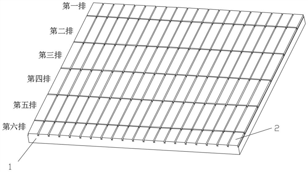
[0019] The interface device for detecting the position of the UAV by resistance, including multiple rows of resistances with different resistance values ​​and a charging plate 1;

[0020] The resistors with different resistance values ​​are resistors with different resistance values;

[0021] see figure 1 , the charging flat panel 1 includes multiple rows of multiple charging contact strips 2, a resistor is arranged between two adjacent charging contact strips 2 in each row, and the resistance value between any two charging contact strips 2 is different;

[0022] The brackets Z on both sides of the drone's landing bracket are connected, and the two charging contact bars 2 are bridged on both sides of the drone bracket after landing.

[0023] During specific implementation, the resistances of the different resistances satisfy the sum of the resistances of any resistance of each row that is not equal to any number of resistances of the remaining resistances (for example: there ...


PUM


Abstract

The invention discloses an interface device for detecting the position of an unmanned aerial vehicle through resistors. The interface device comprises multiple rows of resistors with different resistance values and a charging panel. The resistors with different resistance values are resistors with different resistance values; the charging panel comprises a plurality of rows of charging contact strips, one resistor is arranged between every two adjacent charging contact strips in each row, and the resistance values of any two charging contact strips are different. Two side supports of an unmanned aerial vehicle take-off and landing support are conducted, and two sides of the unmanned aerial vehicle support are bridged with the two charging contact strips after landing. And the resistors with different resistance values meet the condition that the resistance value of any resistor in each row is not equal to the sum of the resistance values of any plurality of residual resistors. And theresistors with different resistance values meet the condition that the sum of any several resistors in each row is not equal to the resistance sum of any plurality of resistors in the residual resistors. The problem of accurate alignment of an existing unmanned aerial vehicle wireless electric energy transmission device with a wireless electric energy transmission device is solved.

Description

technical field [0001] The invention relates to a position detection circuit after a drone lands, in particular to an interface device for resistance detection of the position of the drone. Background technique [0002] At present, with the large number of applications of UAVs, in order to achieve long-term, long-distance or unattended flight missions, wireless charging technology is used to supplement the power of UAVs after landing. The current wireless charging equipment requires a transmitting coil. High-power wireless power transmission can only be achieved by facing the receiving coil at a close distance. However, the landing process of the UAV is affected by the external environment, and the landing accuracy cannot meet the accuracy requirements of the wireless power transmission equipment. The active wireless energy transmission power transmitting device is used to accurately align the receiving coil of the wireless charging device on the drone. This process requires...

Claims


Application Information

Patent Timeline
Patent Type & Authority Applications(China)
IPC IPC(8): B60L53/38B60L53/12H02J50/90H02J50/10
CPCB60L53/38B60L53/12H02J50/90H02J50/10B60L2200/10B64U50/19Y02T10/70Y02T10/7072Y02T90/12Y02T90/14Y02T90/16
Inventor 王家波
Owner 王家波
Learn More