Electric connection seat
A technology of electrical connection and power cord, which is applied in the direction of connection and connection device parts, circuits, etc., which can solve the problems of different lengths of power cords, troubles, and the inability of plug-in strips to be routed directly along the wall.
- Summary
- Abstract
- Description
- Claims
- Application Information
AI Technical Summary
Problems solved by technology
Method used
Image

Examples
Embodiment 1
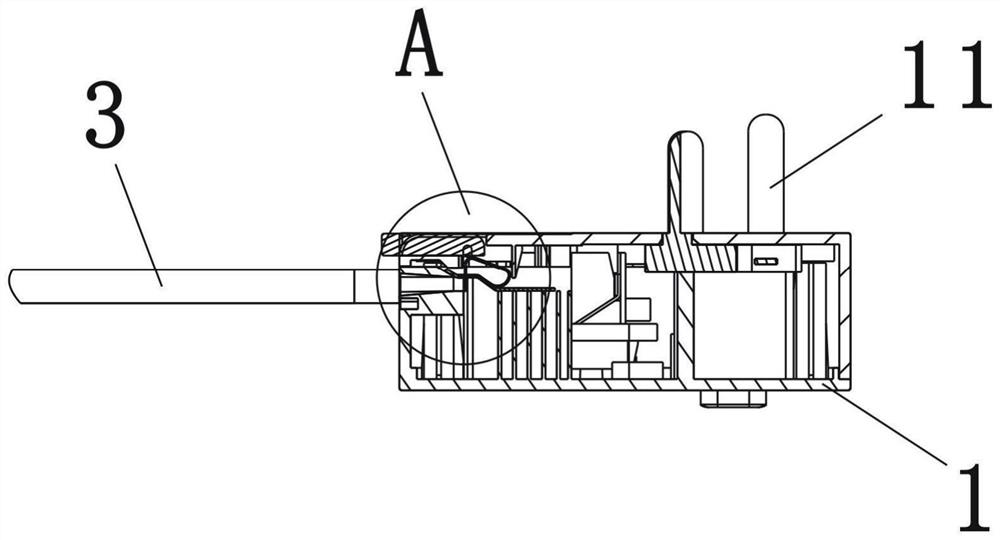
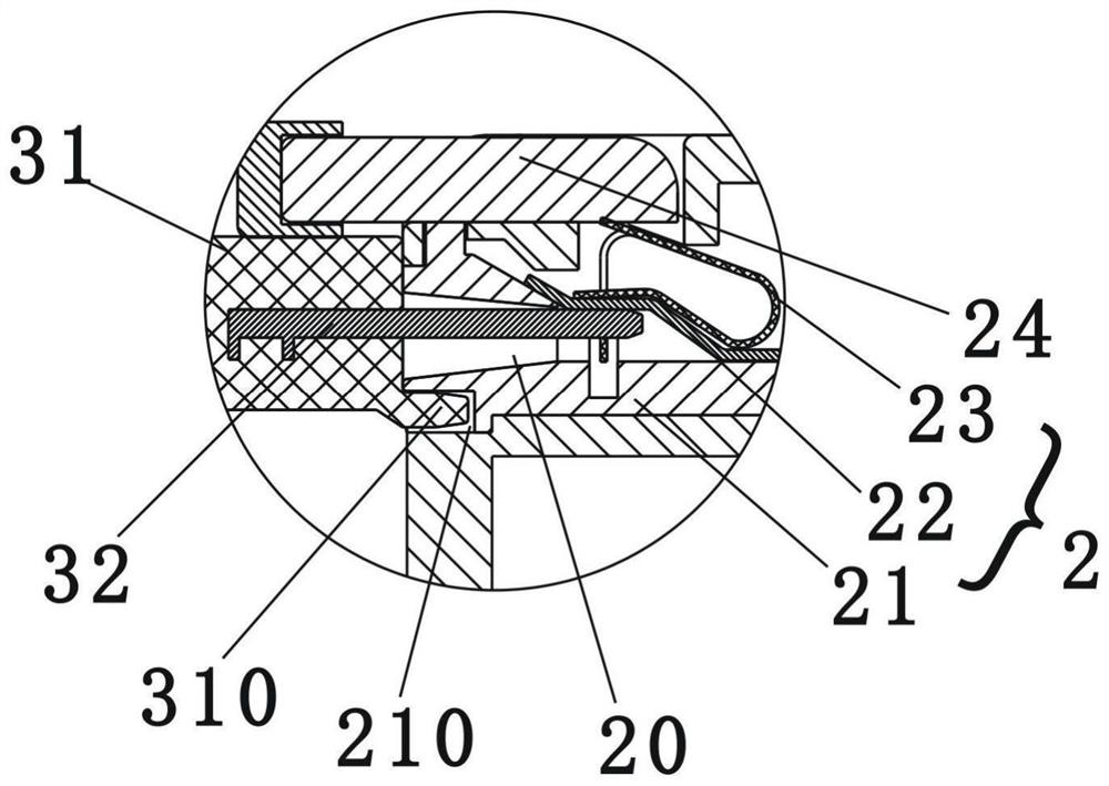
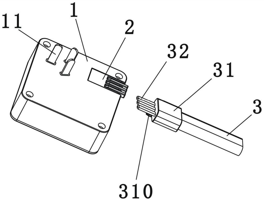
[0032] Such as figure 1 , figure 2 , image 3 Shown is a schematic structural diagram of the first embodiment of the present invention. An electrical connection seat, comprising a box body 1, a terminal 2 fixed in the box body 1, and a power cord 3 electrically connected to the terminal 2, the box body 1 is provided with a plug 11 that matches a wall socket, the The electrical connection seat also includes a clamping structure, which is used for clamping and fixing the power cord 3 when the power cord 3 is inserted into the terminal 2, and for releasing the power cord 3, so that the power cord 3 can be removed from the Pull out from terminal 2.
[0033] In this embodiment, the end of the power cord 3 is provided with a plug connector 31, and the plug connector 31 is provided with three pins 32 respectively connected to the live wire, the neutral wire, and the ground wire. The pins 32 The plug-in connector 31 is pluggably connected to the connection terminal 2 . Moreover,...
Embodiment 2
[0040] Such as Figure 4 Shown is a schematic structural diagram of the second embodiment of the present invention. The difference between this embodiment and Embodiment 1 is that in this embodiment, the clamping structure is a clamping body 7 arranged outside the box body 1 and fixed to the terminal 2, and the clamping body 7 includes an upper The clamping body 71 and the lower clamping body 72 buckled with the upper clamping body 71, the power line 3 outside the terminal 2 is surrounded by the clamping groove formed by the upper clamping body 71 and the lower clamping body 72 70 clamping.
[0041] In this embodiment, the lower clamping body 72 is integrally formed with the housing (not shown in the figure) of the connecting terminal 2, and the upper clamping body 71 is hingedly connected with the lower clamping body 72 through the thin wall 73, and the upper clamping body The tightening body 71 can be flipped over at the hinge relative to the lower clamping body 72 , and t...
Embodiment 3
[0046] Such as Figure 5 Shown is a schematic structural view of the third embodiment of the present invention. The difference between the present embodiment and the second embodiment is that in this embodiment, the clamping body is concealed in the box body, wherein the box body includes a box body 15, and the lower clamping body of the clamping body is the box body 15, and the upper clamping body 16 with a split structure is covered on the box body 15, and the clamping groove 17 is recessed on the surface of the box body 15, when the power cord 3 is installed on the box body, and the upper clamping When the body 16 presses the power cord on the box body 15, the clamping groove 17 is hidden in the box body.
[0047] In this embodiment, the clamping body is installed on the back of the box body. When the plug on the back of the box body is plugged into the wall, the user cannot pull out the power cord due to the clamping body on the box body. The power cord is easy to be sep...
PUM
 Abstract
Description
Claims
Application Information
 - R&D
- Intellectual Property
- Life Sciences
- Materials
- Tech Scout
- Unparalleled Data Quality
- Higher Quality Content
- 60% Fewer Hallucinations
Browse by: Latest US Patents, China's latest patents, Technical Efficacy Thesaurus, Application Domain, Technology Topic, Popular Technical Reports.
© 2025 PatSnap. All rights reserved.Legal|Privacy policy|Modern Slavery Act Transparency Statement|Sitemap|About US| Contact US: help@patsnap.com