Method and system for ratio analysis proximity sensing

A proximity and health monitoring system technology, applied in the system field, can solve problems such as cockpit confusion, incorrect instrument instructions, and ambiguity

Pending Publication Date: 2021-02-09
THE BOEING CO
View PDF11 Cites 0 Cited by
  • Summary
  • Abstract
  • Description
  • Claims
  • Application Information

AI Technical Summary

Problems solved by technology

Uncertain sensor status can lead to ambiguity, incorrect instrument indications and cockpit confusion, control errors, system failures, and additional maintenance work on the ground

Method used


Image

  • Method and system for ratio analysis proximity sensing
  • Method and system for ratio analysis proximity sensing
  • Method and system for ratio analysis proximity sensing

Examples


Embodiment Construction

[0022] For purposes of illustration, systems and methods for ratiometric proximity sensing will now be described in detail. However, not all features of an actual implementation are described in this specification. Those skilled in the art will appreciate that in the development of any such implementation, a number of implementation-specific decisions must be made to achieve the developer's specific goals, such as compliance with system-related constraints and business-related constraints, which will Varies from one implementation to another. In addition, it will be appreciated that such a development effort might be complex and time consuming, but would nevertheless be a routine undertaking for those of ordinary skill in the art having the benefit of this disclosure.

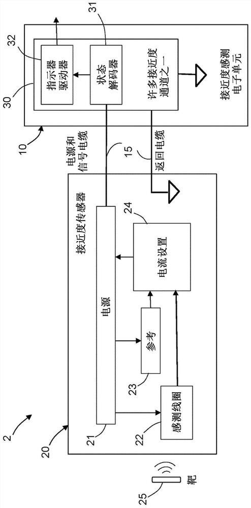
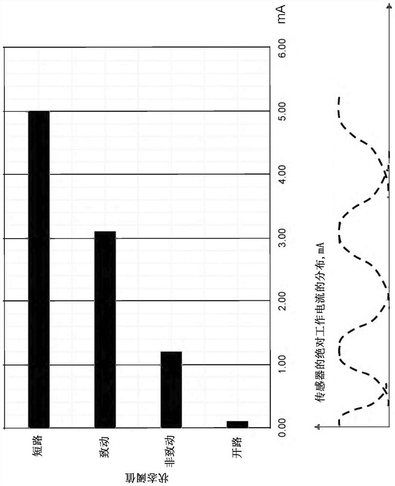
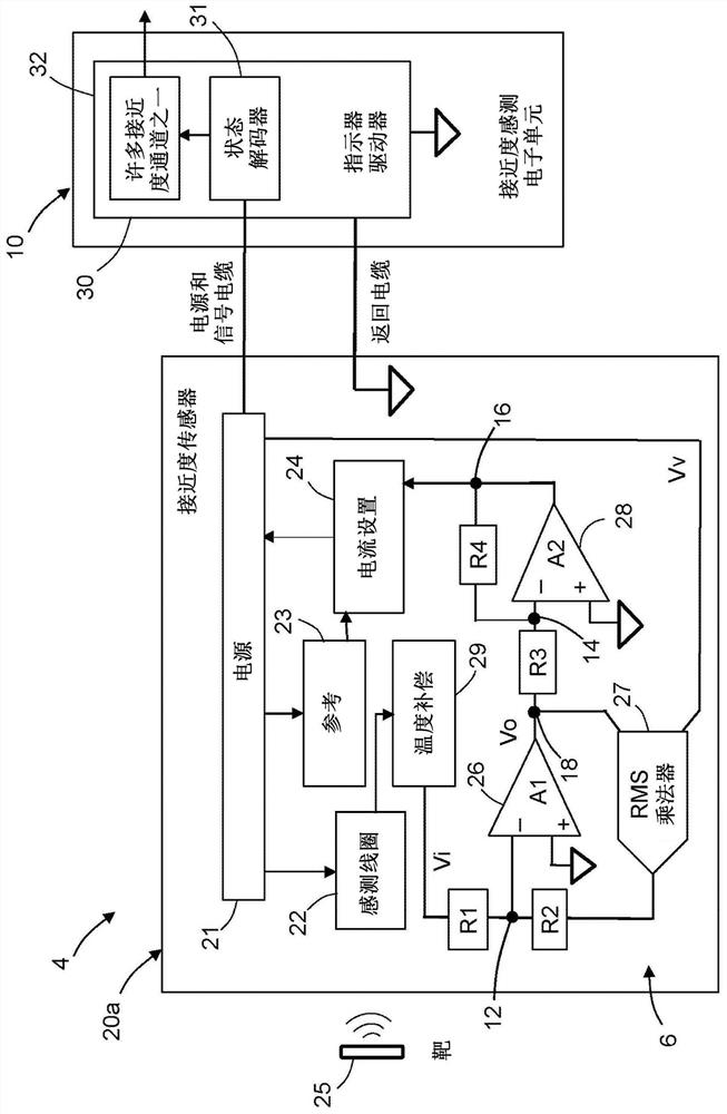
[0023] Existing sensing methods for active proximity sensors are based on measuring the operating current of the sensor in absolute magnitude. figure 1 is a block diagram identifying the components of one exa...


PUM


Abstract

The invention relates to a method and system for ratio analysis proximity sensing. Systems and methods for measuring an operating current and an operating voltage of an inductive proximity sensor in an improved manner are disclosed. The proposed method measures and processes the sensing parameters in a ratiometric analysis manner. The proximity sensing electronics unit receives an input signal from a proximity sensor, the input signal being derived by dividing a sensor current by a sensor supply voltage that generates the operating current. Division results (i.e., quotients) are scaled correctly to represent the state of the sensor. According to the circuit, the working state of the circuit is determined in proportion by eliminating the common mode effect and the change of the state threshold of the sensor, so that other sensing parameters and health states can be measured and monitored without expanding the working range of the sensor.

Description

technical field [0001] The present disclosure relates generally to systems and methods for indicating the proximity of two structural elements or assemblies, and more particularly to a system in which inductive sensors are mounted on fixed assemblies and metal targets are mounted on On deployable components (such as aircraft components). Background technique [0002] Flight control involves movement of inboard and outboard flaps, slats, spoilers, ailerons and other control surfaces. The landing gear retracts after takeoff and deploys during descent. When the wheels touch the ground, the thrust reversers inside the nacelle only turn on after confirming the aircraft's wheel weight status. The position and movement of the aforementioned aircraft components are monitored using on-board proximity sensors and sensor electronics. Typically, proximity sensors are connected to systems in the aircraft's electronics bay by dedicated cables that connect to various locations on the ai...

Claims


Application Information

Patent Timeline
Patent Type & Authority Applications(China)
IPC IPC(8): G01D18/00
CPCG01D18/00H03K17/952H03K17/9502G01D5/2006B64F5/60
Inventor 丰·石
Owner THE BOEING CO
Why Eureka
Try Eureka