
Bionic flapping wing actuating mechanism capable of realizing flapping and torsion composite motion

A compound motion, flapping and twisting technology, applied in the field of micro bionic flapping wing actuators, can solve the problems of difficult manufacturing, difficult miniaturization, low bionic level, etc., and achieves the effect of compact structure, favorable miniaturization and high degree of miniaturization

Inactive Publication Date: 2021-02-09
SHANTOU UNIV
View PDF0 Cites 5 Cited by
  • Summary
  • Abstract
  • Description
  • Claims
  • Application Information

AI Technical Summary

Problems solved by technology

However, the actuators of these flapping wing aircraft either only rely on the passive deformation of the wings to realize the bionic flapping wing mode, and the level of bionics is low; or use mechanisms such as spherical hinges or cams to achieve the combination of flapping and torsional motion, which is difficult to miniaturize and difficult to manufacture; or Improve the maneuverability of the flapping-wing aircraft at the cost of increasing the driving device, but it is also difficult to further miniaturize due to the limitation of the volume and weight of a single driving device

Method used


Image

  • Bionic flapping wing actuating mechanism capable of realizing flapping and torsion composite motion
  • Bionic flapping wing actuating mechanism capable of realizing flapping and torsion composite motion
  • Bionic flapping wing actuating mechanism capable of realizing flapping and torsion composite motion

Examples


Embodiment Construction

[0019] In order to make the object, technical solution and advantages of the present invention clearer, the present invention will be further described in detail below in conjunction with the accompanying drawings.

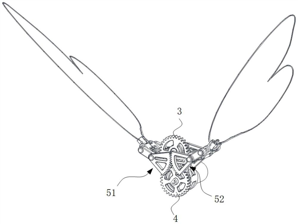
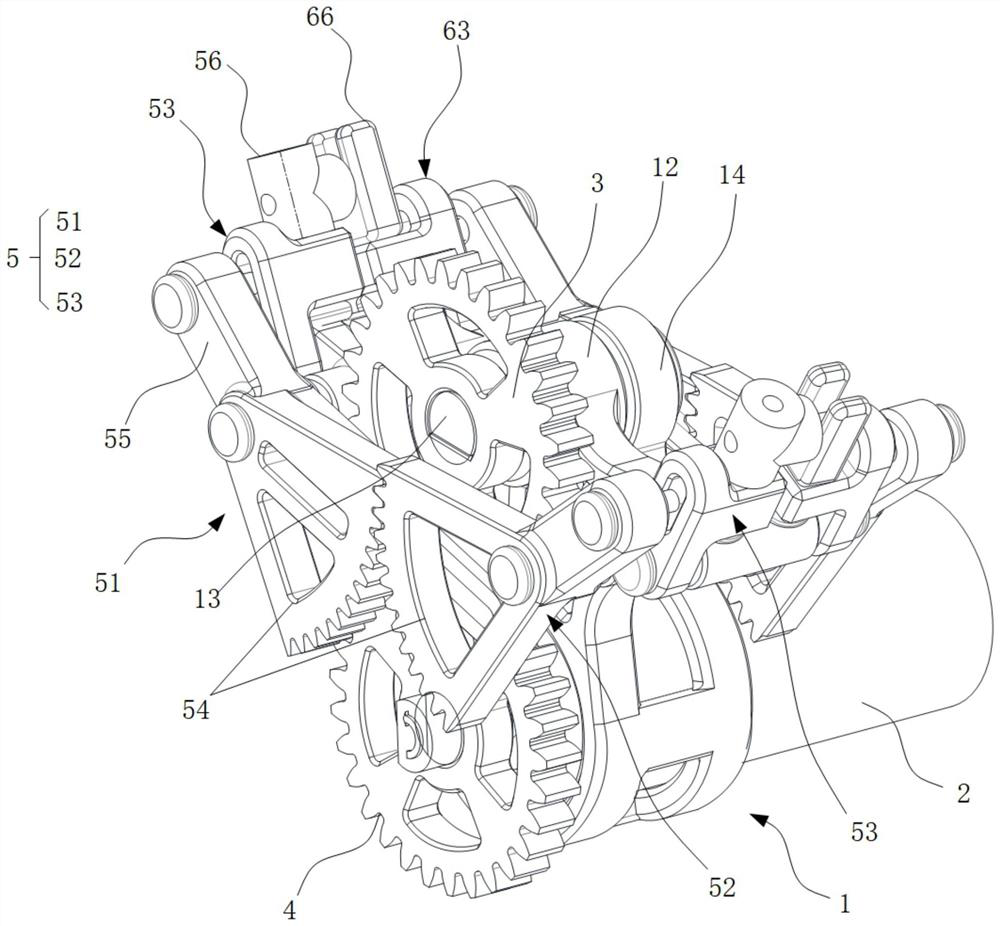
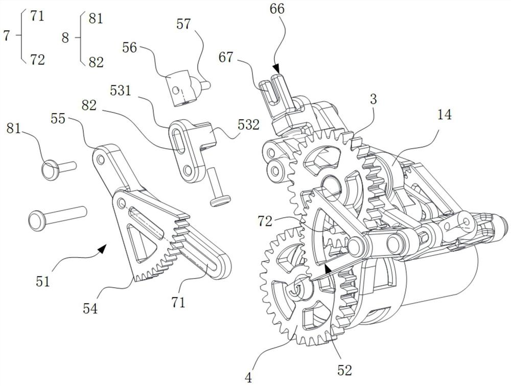
[0020] Such as figure 1 , figure 2 , image 3 shown.

[0021] A bionic flapping-wing actuator that can realize fluttering and twisting compound motions in an embodiment of the present invention includes a frame 1 , a motor 2 , a first gear 3 , a second gear 4 , a main swing mechanism 5 , and an auxiliary swing mechanism 6 .

[0022] The lower part of the frame 1 is provided with a fixed cylinder position 11, the motor 2 is fixedly arranged in the fixed cylinder position 11, the second gear 4 is fixedly connected with the output end of the motor 2, and the upper part of the frame 1 has a swivel seat 12, wherein the rotation is provided with Transmission shaft 13, both sides of transmission shaft 13 protrude from both sides of frame 1 respectively, provide power...


PUM


Abstract

The embodiment of the invention discloses a bionic flapping wing actuating mechanism capable of realizing flapping and torsion composite motion. The actuating mechanism comprises a rack, a motor, a first gear, a main swing mechanism and an auxiliary swing mechanism, the main swing mechanism comprises a left special-shaped gear swing rod, a right special-shaped gear swing rod and linkage swing rods; the first gear and any one of the left special-shaped gear swing rod and the right special-shaped gear swing rod form a first crank swing guide rod mechanism; the linkage swing rods are arranged onthe two sides of the rack in a swing mode respectively, second crank swing guide rod mechanisms are formed between the linkage swing rods and the left special-shaped gear swing rod and between the linkage swing rods and the right special-shaped gear swing rod, and the main swing mechanism and the auxiliary swing mechanism are symmetrical in structure and are arranged on the front side and the rearside of the rack respectively. The auxiliary swing mechanism is in synchronous linkage with the first gear through a transmission shaft. By the adoption of the bionic flapping wing actuating mechanism, the microminiaturization degree is higher, the flapping amplitude is closer to the actual flying level of insects, large-angle active torsion of the wing can be achieved, and the bionic flapping wing actuating mechanism has the very high bionic level and application value.

Description

technical field [0001] The invention relates to a miniature bionic flapping-wing aircraft actuator, in particular to a miniature bionic flapping-wing actuator which utilizes a swing guide mechanism and a different-plane swing rod drive mechanism to realize large-scale fluttering and torsional compound motions. Background technique [0002] The micro flapping wing aircraft is a new type of aircraft developed by imitating the flight of hummingbirds and insects. It has the characteristics of high concealment, small size, low noise and good aerodynamic efficiency. Aerodynamics-related simulation and experimental studies have shown that the compound motion of increasing the flapping amplitude and realizing active flapping and twisting can effectively improve the lift-drag ratio of flapping wing flight, and the coupled motion of wing flapping and twisting is conducive to improving flapping. maneuverability of winged aircraft. As a miniature bionic flapping-wing aircraft, it has h...

Claims


Application Information

Patent Timeline
Patent Type & Authority Applications(China)
IPC IPC(8): B64C33/00B64C33/02
CPCB64C33/00B64C33/02
Inventor 张兴伟陈永辉赵永杰刘麒昊李洁张科
Owner SHANTOU UNIV
Learn More