Connecting mechanism of ultrasonic scalpel and energy converter and ultrasonic scalpel assembly adopting connecting mechanism

A connection mechanism and ultrasonic scalpel technology, applied in the field of medical equipment, can solve problems such as inconvenient operation, unstable torque value, and damage to the performance of transducer cables, so as to improve the daily use time, stable and reliable torque value, and reduce Product Cost Effects

Pending Publication Date: 2021-02-05
SINOSURGICAL HEALTHCARE TECH ZHEJIANG CO LTD
View PDF0 Cites 3 Cited by
  • Summary
  • Abstract
  • Description
  • Claims
  • Application Information

AI Technical Summary

Problems solved by technology

[0004] (1) Each ultrasonic scalpel is provided with a torque wrench, which increases the cost of the device;
[0005] (2) The torque wrench is installed and removed through the front end of the instrument, which is inconvenient to operate;
[0006] (3) The torque wrench needs to be kept properly during use, otherwise it is easy to lose, which is very inconvenient in use;
[0007] (4) The torque wrench is provided by plastic elastic deformation, the torque value is unstable, and the torque value will become smaller and smaller after repeated use, and the plastic shrapnel is easy to break;
[0008] (5) Since the torque wrench is a separate accessory, it may be forgotten to sterilize the wrench during the disinfection process of the ultrasonic knife, so that the ultrasonic knife cannot be connected according to the set requirements and cause inconvenience
[0010] (7) The position of the button is in the two gears of cutting and coagulation. In the actual doctor's operation, most of the time is selected as cutting, and the symmetrical position is designed, and the feeling of fatigue is strong after long-term use;
Repeated high-temperature sterilization will seriously damage the transducer cables, components, and performance

Method used


Image

  • Connecting mechanism of ultrasonic scalpel and energy converter and ultrasonic scalpel assembly adopting connecting mechanism
  • Connecting mechanism of ultrasonic scalpel and energy converter and ultrasonic scalpel assembly adopting connecting mechanism
  • Connecting mechanism of ultrasonic scalpel and energy converter and ultrasonic scalpel assembly adopting connecting mechanism

Examples


Embodiment Construction

[0043] In order to make the object, technical solution and advantages of the present invention clearer, the present invention will be further described in detail below in conjunction with specific embodiments and with reference to the accompanying drawings.

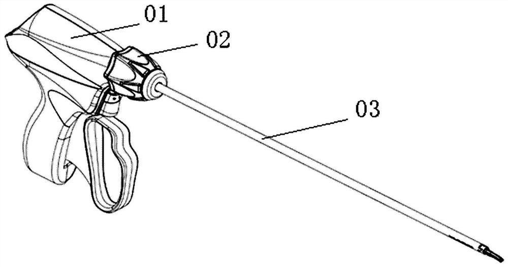
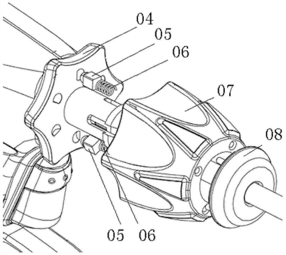
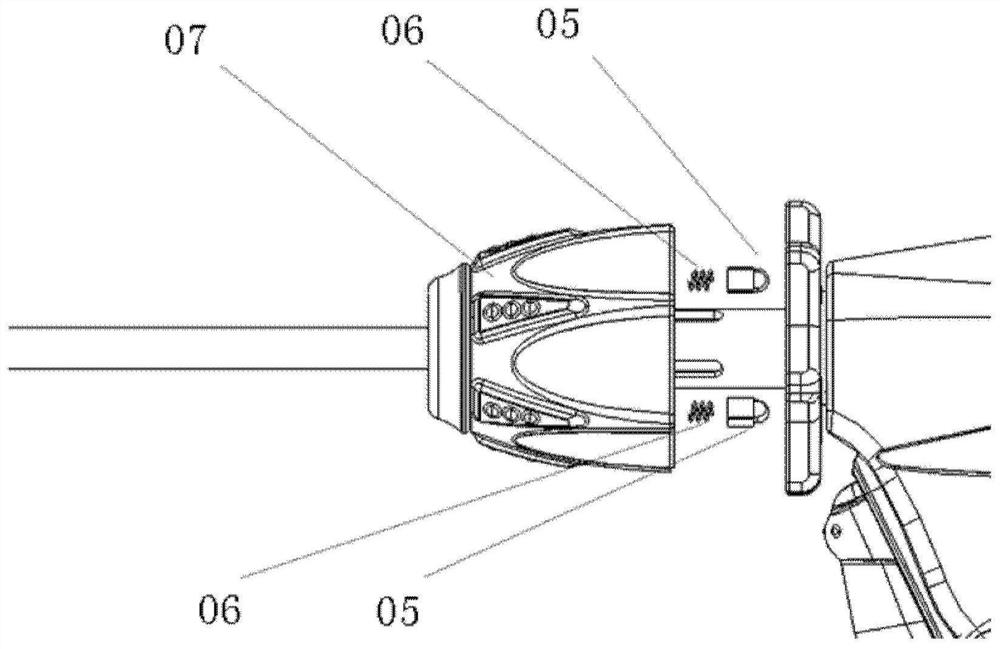
[0044] The invention discloses a connection mechanism between an ultrasonic knife and a transducer, comprising:

[0045] Tighten the turntable, which is a rotating body structure with the insertion direction of the ultrasonic knife as the axis, the axis forms a through hole to cover the ultrasonic knife, and the ultrasonic knife can rotate synchronously with the rotating cap through a pin or a snap-in structure; one end of the tightening turntable is set It has a threaded or snap-fit ​​structure, which is used to connect with the sleeve structure containing the transducer; the other end is a limiting plane with several grooves on it, which are used to cooperate with the torque pin installed on the rotating cap , or, it is...


PUM


Abstract

The invention discloses a connecting mechanism of an ultrasonic scalpel and an energy converter and an ultrasonic scalpel assembly adopting the connecting mechanism. The connecting mechanism comprisesa tightening rotary disc, a rotary cap and a sleeve structure; and the sleeve structure is hollow and can contain the energy converter and a cable, the surface of the sleeve structure can be detachably connected with a sleeve bag and / or a protective film in a sealed mode, and therefore the sleeve structure can be isolated from the outside through the sleeve bag and / or the protective film, and theenergy converter is prevented from being polluted. According to the mechanism, through the design of the sleeve structure, the repeated sterilization frequency of the energy converter can be reducedwhile the sterile operation requirement is met, the damage of repeated instrument sterilization to an instrument is reduced, and the operation of an operator is facilitated.

Description

technical field [0001] The invention relates to the technical field of medical devices, in particular to a connection mechanism between an ultrasonic knife and a transducer and an ultrasonic knife assembly using the same. Background technique [0002] In the application technology of the ultrasonic knife, because the ultrasonic knife head and the transducer are of a separate structure, the two are connected by a threaded joint, and the tightening force needs to be controlled within a certain range during the connection, otherwise the ultrasonic knife cannot work normally, and serious can damage the cutter head or transducer. The commonly used fastening method is to add a set of plastic torque wrench. The torque wrench consists of two parts: the knob body and the rotating shaft. During use, the elastic deformation of the plastic on the rotating shaft is pressed by the knob body to control the tightening force. During the operation, the doctor needs to obliquely observe the s...

Claims


Application Information

Patent Timeline
IPC IPC(8): A61B17/32
CPCA61B17/320068A61B2017/320082A61B2017/320074A61B2560/04A61B2017/320075A61B2017/2929A61B2090/031A61B17/3211
Inventor 黄文星张苗
Owner SINOSURGICAL HEALTHCARE TECH ZHEJIANG CO LTD
Why Eureka
Try Eureka