


Quick Research
Generate reliable direction feasibility study reports for your R&D in just a few steps.

Technical Q&A
Discover and master advanced knowledge NOW. Basics, ideas, possibilities, all at once.

Find Solutions
As an expert in R&D theories, this can generate solutions to your technical problems instantly.

Evaluate Feasibility
Analyze your overall solution with one click, know your potential R&D risks in advance.

Monitor Landscape
Get weekly tech updates, stay abreast of the latest tech innovations and key insights.
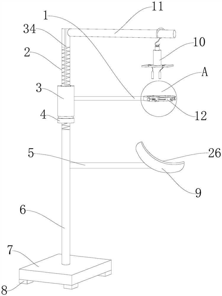
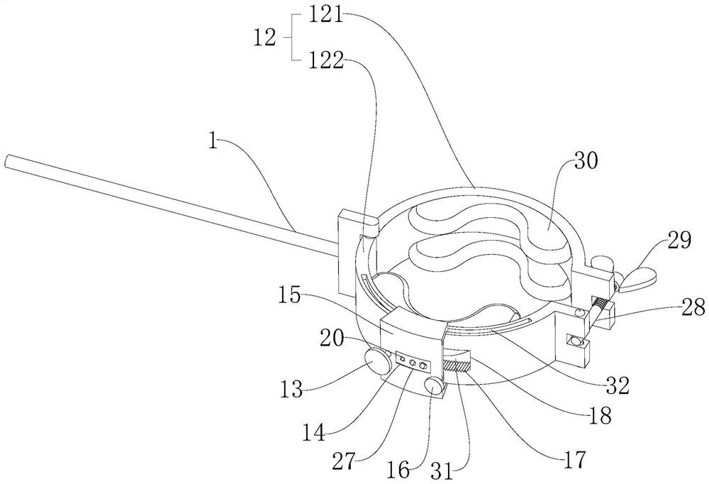
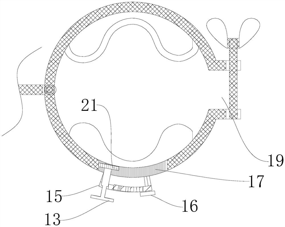
Rapid positioning auxiliary drilling device for carpal bone and forearm far-end surgical operation
A surgical operation and positioning assistance technology, which is applied in the direction of surgery, bone drill guidance, stereotaxic surgical instruments, etc., can solve the problem of inability to meet the rapid positioning requirements of ulnar or radial surgery, the height adjustment of the finger holder is not flexible and convenient, and the comfort of patients To meet the needs of fast positioning, reliable fixation, and improve comfort
- Summary
- Abstract
- Description
- Claims
- Application Information
AI Technical Summary
Problems solved by technology
Method used
Image

Examples
Embodiment Construction
[0038] The present invention will be further described below in conjunction with accompanying drawing:
[0039] Such as Figure 1-Figure 6As shown, the carpal and forearm distal surgical rapid positioning auxiliary drilling device includes a support column 6, an adjustment cylinder 3, an adjustment knob 4 and a fixing ring 12, and a strut 5 is arranged on the side wall of the support column 6, so The support rod 5 is provided with a supporting plate 9 at one end away from the support column 6, the upper end of the support plate 9 is bonded with a liner 26, and the top end of the support column 6 is welded with a screw rod 2 with a symmetrical slideway 34. Said adjustment cylinder 3 runs through said screw rod 2, said adjustment cylinder 3 has a slide bar 35 inserted along track groove 34, said adjustment knob 4 is arranged at the bottom end of said adjustment cylinder 3, said adjustment cylinder 3 A through hole 22 is formed in the inner middle, a screw hole 23 is formed in t...
PUM
 Abstract
Description
Claims
Application Information
 - R&D Engineer
- R&D Manager
- IP Professional
- Industry Leading Data Capabilities
- Powerful AI technology
- Patent DNA Extraction
Browse by: Latest US Patents, China's latest patents, Technical Efficacy Thesaurus, Application Domain, Technology Topic, Popular Technical Reports.
© 2024 PatSnap. All rights reserved.Legal|Privacy policy|Modern Slavery Act Transparency Statement|Sitemap|About US| Contact US: help@patsnap.com